Toyota Venza: Clearance Sonar Main Switch Circuit
DESCRIPTION
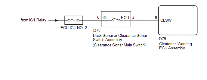
The back sonar or clearance sonar switch assembly is installed at the base of the driver side of the instrument panel.
When the clearance sonar main switch is turned on, an on signal is sent to the clearance warning ECU assembly. The intuitive parking assist system operates according to this signal.
WIRING DIAGRAM
CAUTION / NOTICE / HINT
NOTICE:
Inspect the fuses for circuits related to this system before performing the following inspection procedure.
PROCEDURE
|
1. |
READ VALUE USING TECHSTREAM |
(a) Connect the Techstream to the DLC3.
(b) Turn the engine switch on (IG).
(c) Turn the Techstream on.
(d) Enter the following menus: Body Electrical / Intuitive P/A / Data List.
(e) According to the display on the Techstream, read the Data List.
Intuitive P/A|
Tester Display |
Measurement Item/Range |
Normal Condition |
Diagnostic Note |
|---|---|---|---|
|
Main Switch |
Clearance sonar main switch/OFF or ON |
OFF: Clearance sonar main switch off ON: Clearance sonar main switch on |
- |
|
Clearance Sonar ECU Type |
Type of clearance sonar ECU/Normal |
Normal: Normal clearance sonar type |
- |
|
Result |
Proceed to |
|---|---|
|
Both of the following conditions are met:
|
A |
|
"Normal" is not displayed. |
B |
|
Both of the following conditions are met:
|
C |
| A | .gif) |
PROCEED TO NEXT SUSPECTED AREA SHOWN IN PROBLEM SYMPTOMS TABLE |
| B | |
REPLACE CLEARANCE WARNING ECU ASSEMBLY |
|
.gif)
|
2. |
INSPECT BACK SONAR OR CLEARANCE SONAR SWITCH ASSEMBLY |
(a) Remove the back sonar or clearance sonar switch assembly (See page
.gif) ).
).
|
(b) Measure the resistance according to the value(s) in the table below. Standard Resistance:
|
|
.png)
| NG | |
REPLACE BACK SONAR OR CLEARANCE SONAR SWITCH ASSEMBLY |
|
|
3. |
CHECK HARNESS AND CONNECTOR (BACK SONAR OR CLEARANCE SONAR SWITCH ASSEMBLY POWER SOURCE) |
(a) Measure the voltage according to the value(s) in the table below.
Standard Voltage:
|
Tester Connection |
Condition |
Specified Condition |
|---|---|---|
|
D78-6 (IG) - Body ground |
Engine switch on (IG) |
11 to 14 V |
|
D78-6 (IG) - Body ground |
Engine switch off |
Below 1 V |
| NG | |
REPAIR OR REPLACE HARNESS OR CONNECTOR |
|
|
4. |
CHECK HARNESS AND CONNECTOR (BACK SONAR OR CLEARANCE SONAR SWITCH ASSEMBLY - CLEARANCE WARNING ECU ASSEMBLY) |
(a) Disconnect the D79 clearance warning ECU assembly connector.
(b) Measure the resistance according to the value(s) in the table below.
Standard Resistance:
|
Tester Connection |
Condition |
Specified Condition |
|---|---|---|
|
D79-9 (CLSW) - D78-3 (ECU) |
Always |
Below 1 Ω |
|
D79-9 (CLSW) - Body ground |
Always |
10 kΩ or higher |
| OK | |
REPLACE CLEARANCE WARNING ECU ASSEMBLY |
| NG | |
REPAIR OR REPLACE HARNESS OR CONNECTOR |
 Front Right Sensor Malfunction (C1AE4)
DESCRIPTION
The No. 1 ultrasonic sensor (front right sensor) is installed on the front bumper.
The ECU detects obstacles based on signals received from the No. 1 ultrasonic sensor
(front right se ...
 Clearance Warning Buzzer Circuit
DESCRIPTION
This circuit consists of the No. 1 clearance warning buzzer and clearance warning
ECU assembly. An ECU-excited type buzzer is used. The ECU operates the buzzer using
a sound pattern t ...
Other materials about Toyota Venza:
If your vehicle needs to be towed
If towing is necessary, we recommend having your vehicle towed by your Toyota
dealer or a commercial towing service, using a lift-type truck or a flat bed truck.
Use a safety chain system for all towing, and abide by all state/provincial and
local laws.
...
Ambient Temperature Sensor
Components
COMPONENTS
ILLUSTRATION
Inspection
INSPECTION
PROCEDURE
1. INSPECT AMBIENT TEMPERATURE SENSOR
(a) Measure the resistance according to the value(s) in the table below.
Standard Resistance:
Tester Connection
C ...
Initialization
INITIALIZATION
1. RESET BACK DOOR CLOSE POSITION
NOTICE:
Perform initialization of the power back door system (power back door ECU initialization)
if one of the following is performed:
The cable is disconnected from the negative (-) battery termin ...

0.1441