Toyota Venza: TC and CG Terminal Circuit
DESCRIPTION
Connecting terminals TC and CG of the DLC3 causes the system to enter self-diagnostic mode. If a malfunction is present, the MIL will blink.
HINT:
When a particular warning light remains blinking, a ground short in the wiring of terminal TC of the DLC3 or an internal ground short in the relevant ECU is suspected.
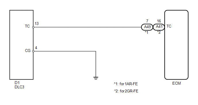
WIRING DIAGRAM
PROCEDURE
|
1. |
CHECK HARNESS AND CONNECTOR (DLC3 - ECM) |
(a) Disconnect the ECM connector.
(b) Measure the resistance according to the value(s) in the table below.
Standard Resistance:
For 1AR-FE|
Tester Connection |
Condition |
Specified Condition |
|---|---|---|
|
D1-13 (TC) - A49-7 (TC) |
Always |
Below 1 Ω |
|
Tester Connection |
Condition |
Specified Condition |
|---|---|---|
|
D1-13 (TC) - A41-16 (TC) |
Always |
Below 1 Ω |
|
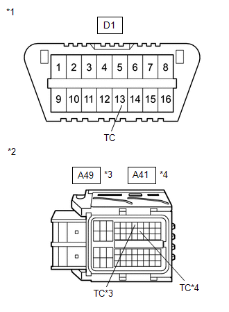
*1 |
DLC3 |
|
*2 |
Front view of wire harness connector (to ECM) |
|
*3 |
for 1AR-FE |
|
*4 |
for 2GR-FE |
(c) Reconnect the ECM connector.
| NG | .gif) |
REPAIR OR REPLACE HARNESS OR CONNECTOR (DLC3 - ECM) |
|
.gif)
|
2. |
CHECK HARNESS AND CONNECTOR (DLC3 - BODY GROUND) |
(a) Measure the resistance according to the value(s) in the table below.
Standard Resistance:
|
Tester Connection |
Condition |
Specified Condition |
|---|---|---|
|
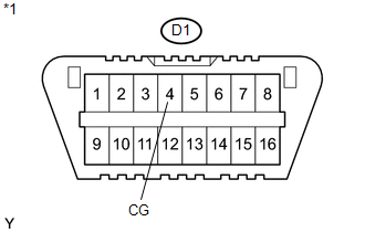
D1-4 (CG) - Body ground |
Always |
Below 1 Ω |
|
*1 |
DLC3 |
| NG | |
REPAIR OR REPLACE HARNESS OR CONNECTOR (DLC3 - BODY GROUND) |
|
|
3. |
CHECK HARNESS AND CONNECTOR (DLC3 - BODY GROUND) |
(a) Measure the resistance according to the value(s) in the table below.
Standard Resistance:
|
Tester Connection |
Condition |
Specified Condition |
|---|---|---|
|
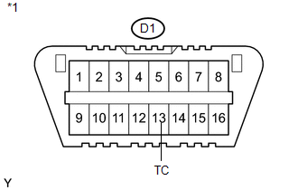
D1-13 (TC) - Body ground |
Always |
10 kΩ or higher |
|
*1 |
DLC3 |
| OK | |
PROCEED TO NEXT SUSPECTED AREA SHOWN IN PROBLEM SYMPTOMS TABLE |
| NG | |
REPAIR OR REPLACE HARNESS OR CONNECTOR OR EACH ECU |
 Cruise SET Indicator Light Circuit
DESCRIPTION
The ECM detects a cruise control switch signal and sends it to the combination
meter assembly through CAN. Then the SET indicator light comes on.
The SET indicator light ci ...

Other materials about Toyota Venza:
Installation
INSTALLATION
PROCEDURE
1. INSTALL POWER OUTLET SOCKET COVER NO.1
(a) Engage the 2 claws to install the power point socket cover.
2. INSTALL POWER POINT SOCKET ASSEMBLY
(a) Engage the 2 c ...
All Doors LOCK/UNLOCK Functions do not Operate Via Door Control Switch
DESCRIPTION
The main body ECU (driver side junction block assembly) receives switch signals
from the door control switch and activates the door lock motor on each door according
to these signals.
WIRING DIAGRAM
PROCEDURE
1.
REA ...
Removal
REMOVAL
CAUTION / NOTICE / HINT
HINT:
The front side fix window assembly can be reused. When installing the
window, if any of the clips on the front side fix window assembly are broken,
butyl tape can be used to support the glass until the a ...

0.1414