Toyota Venza: Installation
INSTALLATION
PROCEDURE
1. INSTALL TIMING CHAIN COVER SUB-ASSEMBLY
|
(a) Apply a light coat of engine oil to 2 new oil pump gaskets and new oil hole cover gasket. |
|
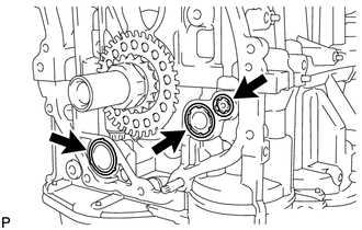
(b) Install the 2 new oil pump gaskets and new oil hole cover gasket to the stiffening crankcase.
|
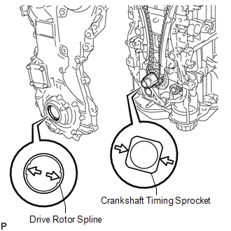
(c) Align the drive rotor spline and the crankshaft timing sprocket as shown in the illustration. |
|
(d) Apply seal packing in a line to the timing chain cover sub-assembly as shown in the following illustration.
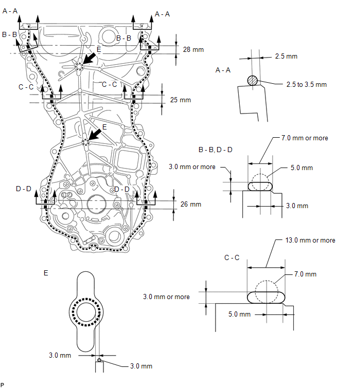
Seal packing:
Toyota Genuine Seal Packing Black, Three Bond 1207B or equivalent.
Seal Packing Application Chart:
|
Area |
Seal Packing Diameter (Round) |
Distance from Edge of Cover to Center of Seal Packing |
Seal Packing Application Length |
|---|---|---|---|
|
Seal Packing Dimension (Flat) |
|||
|
Dashed Line |
2.5 to 3.5 mm (0.0984 to 0.138 in.) |
2.5 mm (0.0984 in.) |
- |
|
- |
|||
|
A - A |
2.5 to 3.5 mm (0.0984 to 0.138 in.) |
2.5 mm (0.0984 in.) |
- |
|
- |
|||
|
B - B |
5.0 mm (0.197 in.) |
3.0 mm (0.118 in.) |
28 mm (1.10 in.) |
|
7.0 mm (0.276 in.) or more wide and 3.0 mm (0.118 in.) or more thick |
|||
|
C - C |
7.0 mm (0.276 in.) |
5.0 mm (0.197 in.) |
25 mm (0.984 in.) |
|
13.0 mm (0.512 in.) or more wide and 3.0 mm (0.118 in.) or more thick |
|||
|
D - D |
5.0 mm (0.197 in.) |
3.0 mm (0.118 in.) |
26 mm (1.02 in.) |
|
7.0 mm (0.276 in.) or more wide and 3.0 mm (0.118 in.) or more thick |
|||
|
E |
3.0 mm (0.118 in.) |
3.0 mm (0.118 in.) |
- |
|
- |
NOTICE:
- When the contact surfaces are wet, clean the surfaces with non-residue solvent before applying seal packing.
- Install the timing chain cover sub-assembly within 3 minutes and tighten the bolts within 10 minutes after applying seal packing.
- After applying seal packing to the timing chain cover sub-assembly, install the engine mounting bracket RH within 10 minutes.
- Do not apply oil for at least 4 hours after the installation.
- Do not start the engine for at least 4 hours after the installation.
|
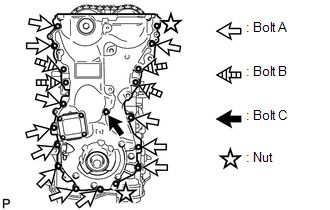
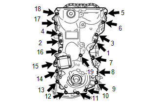
(e) Temporarily install the timing chain cover sub-assembly with the 17 bolts and 2 nuts. Bolt Length:
NOTICE: Make sure there is no oil on the bolts. If there is oil on the bolts, clean them before installing them. |
|
|
(f) Tighten the 17 bolts and 2 nuts in several steps, in the sequence shown in the illustration. Torque: for bolt 1, 2, 3 and 4 : 55 N·m {561 kgf·cm, 41 ft·lbf} except bolt 1, 2, 3 and 4 : 21 N·m {214 kgf·cm, 15 ft·lbf} |
|
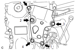
2. INSTALL ENGINE MOUNTING BRACKET RH
|
(a) Install the engine mounting bracket RH, and install the 5 bolts in the order shown in the illustration. Torque: for bolt 1, 2 and 3 : 55 N·m {561 kgf·cm, 41 ft·lbf} for bolt 4 and 5 : 21 N·m {214 kgf·cm, 15 ft·lbf} NOTICE: After applying seal packing to the timing chain cover sub-assembly, install the engine mounting bracket RH within 10 minutes. |
|
3. INSTALL TIMING CHAIN COVER OIL SEAL
.gif)
4. INSTALL CRANKSHAFT PULLEY
5. INSTALL CRANKSHAFT POSITION SENSOR
6. INSTALL V-RIBBED BELT TENSIONER ASSEMBLY
7. INSTALL CYLINDER HEAD COVER SUB-ASSEMBLY
8. INSTALL IGNITION COIL ASSEMBLY
9. REMOVE ENGINE STAND
(See page )
 Components
COMPONENTS
ILLUSTRATION
...
 Removal
REMOVAL
CAUTION / NOTICE / HINT
NOTICE:
Do not remove the oil pump or oil pump relief valve from the timing chain cover
sub-assembly.
PROCEDURE
1. INSTALL ENGINE ON ENGINE STAND
(See page )
...
Other materials about Toyota Venza:
Detection range of the sensors
1. Approximately 1.6 ft. (50 cm)
2. Approximately 4.9 ft. (150 cm)
3. Approximately 2.0 ft. (60 cm)
The diagram shows the detection range of the sensors. Note that the sensors cannot
detect obstacles that are extremely close to the vehicle.
The range o ...
Installation
INSTALLATION
PROCEDURE
1. INSTALL STEERING INTERMEDIATE SHAFT ASSEMBLY
(a) Align the matchmarks on the steering intermediate shaft assembly
and the steering column assembly.
Text in Illustration
*1
Matc ...
Inspection
INSPECTION
CAUTION / NOTICE / HINT
HINT:
Use the same procedure for the intake side and exhaust side.
PROCEDURE
1. INSPECT CAMSHAFT TIMING OIL CONTROL VALVE ASSEMBLY
(a) Measure the resistance according to the value(s) in the table below.
S ...

0.1408