Toyota Venza: Components
COMPONENTS
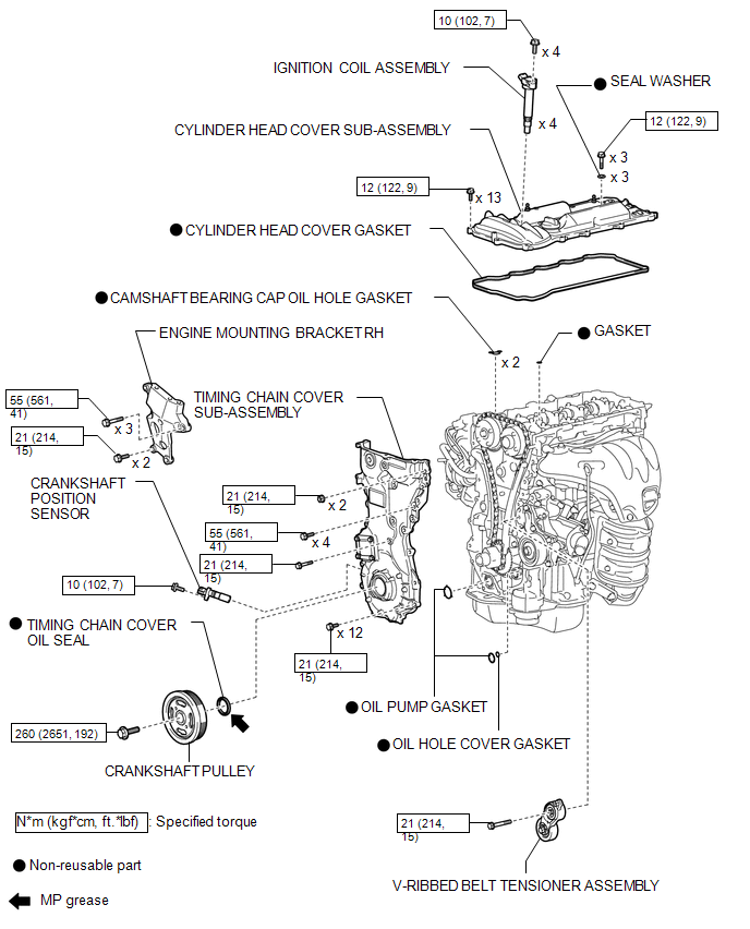
ILLUSTRATION
 Oil Pump
...
 Installation
INSTALLATION
PROCEDURE
1. INSTALL TIMING CHAIN COVER SUB-ASSEMBLY
(a) Apply a light coat of engine oil to 2 new oil pump gaskets and new
oil hole cover gasket.
...
Other materials about Toyota Venza:
Installation
INSTALLATION
PROCEDURE
1. INSTALL REAR DOOR UPPER WINDOW FRAME MOULDING
(a) Engage the guide and install the rear door upper window frame moulding
to the door frame.
(b) Using an air riveter or ...
Vehicle Speed Signal Circuit between Radio Receiver and Combination Meter
DESCRIPTION
for Automatic Sound Levelizer (ASL):
This circuit is necessary for the Automatic Sound Levelizer (ASL) built
into the radio and display receiver assembly.
The Automatic Sound Levelizer (ASL) function automatically adjusts the
a ...
Customize Parameters
CUSTOMIZE PARAMETERS
1. CUSTOMIZING FUNCTION WITH TECHSTREAM (REFERENCE)
HINT:
When the customer requests a change in a function, first make sure that
the function can be customized.
Be sure to make a note of the current settings before cust ...

0.1294