Toyota Venza: Inspection
INSPECTION
CAUTION / NOTICE / HINT
HINT:
Use the same procedure for the intake side and exhaust side.
PROCEDURE
1. INSPECT CAMSHAFT TIMING OIL CONTROL VALVE ASSEMBLY
|
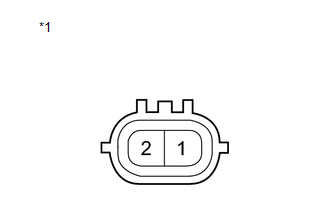
(a) Measure the resistance according to the value(s) in the table below. Standard Resistance:
If the result is not as specified, replace the oil control valve assembly. Text in Illustration
|
|
|
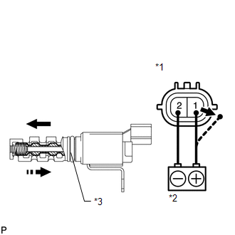
(b) Connect the positive (+) lead from a battery to terminal 1 and the negative (-) lead to terminal 2, and check the movement of the valve. OK:
NOTICE: Confirm that the valve moves freely and does not stick in any position. If necessary, replace the camshaft timing oil control valve assembly. HINT: Accumulation of foreign matter can cause minor pressure leaks. Minor pressure leaks will cause the camshaft to advance or retard, and this will cause a DTC to be set. Text in Illustration
|
|
 Removal
REMOVAL
PROCEDURE
1. REMOVE NO. 1 ENGINE COVER SUB-ASSEMBLY
2. REMOVE CAMSHAFT TIMING OIL CONTROL VALVE ASSEMBLY (for Exhaust Side)
(a) Disconnect the oil control valve connector.
...
 Installation
INSTALLATION
PROCEDURE
1. INSTALL CAMSHAFT TIMING OIL CONTROL VALVE ASSEMBLY (for Exhaust Side)
(a) Apply a light coat of engine oil to a new O-ring, and install it
to the oil contro ...
Other materials about Toyota Venza:
Rear seats
Seatback angle adjustment lever
Pull up the lever until the lock is completely released.
Folding down the rear seatbacks
- Before folding down the rear seatbacks
Stow the seat belt buckles and lower the head restraints to the lowest position.
...
Removal
REMOVAL
PROCEDURE
1. RECOVER REFRIGERANT FROM REFRIGERATION SYSTEM
2. DISCHARGE FUEL SYSTEM PRESSURE
3. PLACE FRONT WHEELS FACING STRAIGHT AHEAD
4. REMOVE FRONT WHEELS
5. DISCONNECT CABLE FROM NEGATIVE BATTERY TERMINAL
NOTICE:
When disconnecting ...
How To Proceed With Troubleshooting
CAUTION / NOTICE / HINT
HINT:
Use the following procedure to troubleshoot the cruise control system.
*: Use the Techstream.
PROCEDURE
1.
VEHICLE BROUGHT TO WORKSHOP
NEXT
...

0.1154