Toyota Venza: Installation
INSTALLATION
PROCEDURE
1. INSTALL STEERING INTERMEDIATE SHAFT ASSEMBLY
|
(a) Align the matchmarks on the steering intermediate shaft assembly and the steering column assembly. Text in Illustration
|
|
.png)
|
(b) Install the bolt. Torque: 35 N·m {360 kgf·cm, 26 ft·lbf} |
|
.png)
2. INSTALL STEERING POST ASSEMBLY
|
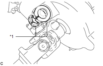
(a) Check that the 2 bushings are securely installed to the steering post assembly. Text in Illustration
HINT: If the bushings are missing or damaged, replace the steering column assembly with a new one. |
|
|
(b) Install the steering post assembly with the bolt and 2 nuts. Torque: 25 N·m {255 kgf·cm, 18 ft·lbf} NOTICE:
|
|
.png)
(c) Connect the connectors and engage the wire harness clamps to the steering post assembly.
|
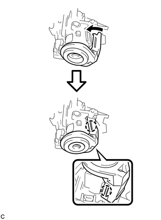
(d) Connect the connector to the power steering ECU assembly. HINT: Return the lock lever to its original position to connect the connector, and then securely push in the lock of the lock lever as shown in the illustration. |
|
.png)
|
(e) Connect the connector to the power steering ECU assembly. |
|
.png)
3. CONNECT STEERING INTERMEDIATE SHAFT ASSEMBLY
|
(a) Align the matchmarks on the steering intermediate shaft assembly and the power steering link assembly. Text in Illustration
|
|
.png)
|
(b) Install the bolt. Torque: 35 N·m {360 kgf·cm, 26 ft·lbf} |
|
.png)
|
(c) Tighten the clamp. |
|
4. INSTALL FRONT WHEEL LH
Torque:
103 N·m {1050 kgf·cm, 76 ft·lbf}
5. INSTALL TRANSPONDER KEY AMPLIFIER (w/o Smart Key System)
|
(a) Connect the connector to the transponder key amplifier. |
|
.png)
(b) Align the transponder key amplifier with the steering column upper bracket. Tilt the amplifier slightly and slide it into position.
|
(c) Push the transponder key amplifier, and engage the 2 claws to install the transponder key amplifier to the steering column upper bracket. |
|
6. INSTALL TURN SIGNAL SWITCH ASSEMBLY WITH SPIRAL CABLE SUB-ASSEMBLY
|
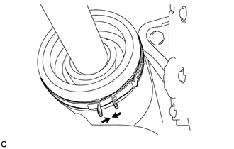
(a) Using pliers, expand the clamp. Text in Illustration
|
|
.png)
(b) While holding the clamp expanded, install the turn signal switch assembly with spiral cable sub-assembly to the steering column assembly and engage the claw.
(c) Return the clamp to its original position.
(d) Connect the connectors to the turn signal switch assembly with spiral cable sub-assembly.
7. INSTALL UPPER STEERING COLUMN COVER
|
(a) Engage the 4 clips and 2 guides to install the upper steering column cover onto the instrument panel cluster finish panel. |
|
.png)
|
(b) Engage the claw to install the upper steering column cover. |
|
.png)
8. INSTALL LOWER STEERING COLUMN COVER
|
(a) Engage the 2 claws to install the lower steering column cover. |
|
.png)
(b) Install the 2 screws.
Torque:
2.0 N·m {20 kgf·cm, 18 in·lbf}
9. INSTALL DRIVER SIDE KNEE AIRBAG ASSEMBLY
(See page .gif) )
)
10. TURN FRONT WHEELS TO FACE STRAIGHT AHEAD
11. ADJUST SPIRAL CABLE WITH SENSOR SUB-ASSEMBLY
12. INSTALL STEERING WHEEL ASSEMBLY
13. INSPECT STEERING WHEEL CENTER POINT
14. INSTALL STEERING PAD
15. KEY REGISTRATION (w/ Smart Key System)
(a) When replacing the steering lock actuator assembly, perform the key registration
(See page ).
16. INITIALIZE ROTATION ANGLE SENSOR AND CALIBRATE TORQUE SENSOR ZERO POINT
(a) When replacing the steering column assembly, clear the rotation angle sensor
calibration value, initialize the rotation angle sensor, and calibrate the torque
sensor zero point (See page ).
 Reassembly
REASSEMBLY
CAUTION / NOTICE / HINT
NOTICE:
When using a vise, do not overtighten it.
PROCEDURE
1. INSTALL STEERING LOCK ACTUATOR ASSEMBLY (w/ Smart Key System)
(a) Secure the steering column ass ...

Other materials about Toyota Venza:
Solar Sensor
Components
COMPONENTS
ILLUSTRATION
On-vehicle Inspection
ON-VEHICLE INSPECTION
PROCEDURE
1. INSPECT SOLAR SENSOR
(a) Disconnect the solar sensor connector.
(b) Measure the voltage accordin ...
Removal
REMOVAL
PROCEDURE
1. REMOVE COOL AIR INTAKE DUCT SEAL
2. REMOVE INLET NO. 2 AIR CLEANER
3. REMOVE AIR CLEANER CAP WITH HOSE
4. REMOVE AIR CLEANER CASE
5. REMOVE AIR CLEANER BRACKET
(a) Separate the wire harness clamp.
...
Front Passenger Side Power Window Auto Up / Down Function does not Operate with
Front Passenger Side Power Window Switch
DESCRIPTION
If the manual up/down function can be performed but the auto up/down function
cannot, the fail-safe mode may be functioning.
If the power window initialization (See page
) has not been performed, the auto up/down function
will not operate.
...

0.1718