Toyota Venza: Removal
REMOVAL
CAUTION / NOTICE / HINT
NOTICE:
Do not remove the oil pump or oil pump relief valve from the timing chain cover sub-assembly.
PROCEDURE
1. INSTALL ENGINE ON ENGINE STAND
(See page .gif) )
)
2. REMOVE IGNITION COIL ASSEMBLY
3. REMOVE CYLINDER HEAD COVER SUB-ASSEMBLY
4. REMOVE CRANKSHAFT POSITION SENSOR
5. REMOVE CRANKSHAFT PULLEY
6. REMOVE ENGINE MOUNTING BRACKET RH
|
(a) Remove the 5 bolts and engine mounting bracket RH. |
|
7. REMOVE V-RIBBED BELT TENSIONER ASSEMBLY
8. REMOVE TIMING CHAIN COVER SUB-ASSEMBLY
|
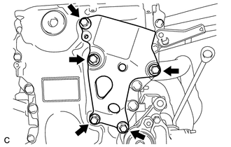
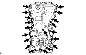
(a) Remove the 17 bolts and 2 nuts. |
|
(b) Remove the timing chain cover sub-assembly by prying between the timing chain cover sub-assembly and cylinder head, camshaft housing, cylinder block and stiffening crankcase with a screwdriver as shown in the illustration.
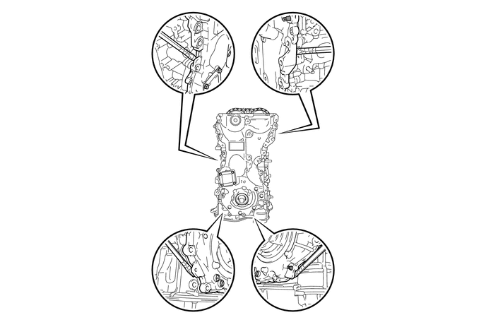
NOTICE:
Be careful not to damage the contact surfaces of the cylinder head, camshaft housing, cylinder block, stiffening crankcase and timing chain cover sub-assembly.
HINT:
Tape the screwdriver tip before use.
|
(c) Remove the 2 oil pump gaskets and oil hole cover gasket from the stiffening crankcase. |
|
.png)
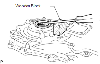
9. REMOVE TIMING CHAIN COVER OIL SEAL
|
(a) Using a screwdriver and wooden block, pry out the timing chain cover oil seal. NOTICE: Do not damage the surface of the timing chain cover oil seal press fit hole. HINT: Tape the screwdriver tip before use. |
|
 Installation
INSTALLATION
PROCEDURE
1. INSTALL TIMING CHAIN COVER SUB-ASSEMBLY
(a) Apply a light coat of engine oil to 2 new oil pump gaskets and new
oil hole cover gasket.
...
 1ar-fe Starting
...
Other materials about Toyota Venza:
Evaporative Emission Control System Pressure Sensor Range / Performance (P0451-P0453)
DTC SUMMARY
DTC No.
Monitoring Item
Malfunction Detection Condition
Trouble Area
Detection Timing
Detection Logic
P0451
Canister pressure sensor abnormal voltage flu ...
System Description
SYSTEM DESCRIPTION
1. ILLUMINATED ENTRY SYSTEM
(a) The illuminated entry system has the following control functions:
Control
Outline
Lights that Operate
Actuation Area-linked*2
When a registered k ...
Operation Check
OPERATION CHECK
1. CHECK WINDOW LOCK SWITCH
HINT:
Before performing the window lock switch operation check, make sure that the
window lock switch is off (the switch is not pushed in).
(a) Check that the front passenger and rear windows cannot be operat ...

0.1577