Toyota Venza: Removal
REMOVAL
PROCEDURE
1. REMOVE FRONT WHEELS
2. REMOVE FRONT STABILIZER LINK ASSEMBLY LH
|
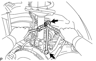
(a) Remove the 2 nuts and front stabilizer link assembly LH. HINT: If the ball joint turns together with the nut, use a hexagon wrench (6 mm) to hold the stud bolt. |
|
3. REMOVE FRONT STABILIZER LINK ASSEMBLY RH
HINT:
Perform the same procedure as for the LH side.
4. REMOVE FRONT FRAME ASSEMBLY
for 1AR-FE: (See page .gif) )
)
for 2GR-FE: (See page )
5. REMOVE STEERING LINK ASSEMBLY
6. REMOVE FRONT STABILIZER BAR
(a) Remove the front stabilizer bar from the vehicle.
7. REMOVE FRONT NO. 1 STABILIZER BRACKET LH
(a) Remove the front No. 1 stabilizer bracket LH from the front No. 1 stabilizer bar bushing.
8. REMOVE FRONT NO. 1 STABILIZER BRACKET RH
HINT:
Perform the same procedure as for the LH side.
9. REMOVE FRONT NO. 2 STABILIZER BRACKET LH
|
(a) Remove the front No. 2 stabilizer bracket LH from the front No. 1 stabilizer bar bushing. |
|
.png)
10. REMOVE FRONT NO. 2 STABILIZER BRACKET RH
HINT:
Perform the same procedure as for the LH side.
11. REMOVE FRONT NO. 1 STABILIZER BAR BUSHING
(a) Remove the 2 front No. 1 stabilizer bar bushings from the front stabilizer bar.
 Components
COMPONENTS
ILLUSTRATION
...
 Inspection
INSPECTION
PROCEDURE
1. INSPECT FRONT STABILIZER LINK ASSEMBLY
(a) Inspect the turning torque of the ball joint.
(1) Secure the front stabilizer link assembly in a vise using aluminum ...
Other materials about Toyota Venza:
Installation
INSTALLATION
CAUTION / NOTICE / HINT
HINT:
Use the same procedure for the RH side and LH side.
The procedure listed below is for the LH side.
PROCEDURE
1. INSTALL REAR POWER WINDOW REGULATOR MOTOR ASSEMBLY
NOTICE:
The regulator arm mus ...
Disassembly
DISASSEMBLY
PROCEDURE
1. REMOVE TRANSPONDER KEY ECU ASSEMBLY (w/ Engine Immobiliser System)
2. REMOVE NO. 1 FINISH PANEL MOUNTING BRACKET
(a) Remove the 2 bolts and 2 No. 1 finish panel mounting brackets as
shown in the illustration.
...
Side doors
The vehicle can be locked and unlocked using the entry function, wireless
remote control, key or door lock switch.
- Entry function (vehicles with smart key system)
- Wireless remote control
- Key
► Vehicles with smart key system ...

0.1397