Toyota Venza: Removal
REMOVAL
PROCEDURE
1. REMOVE NO. 1 ENGINE COVER SUB-ASSEMBLY
.gif)
2. REMOVE CAMSHAFT TIMING OIL CONTROL VALVE ASSEMBLY (for Exhaust Side)
|
(a) Disconnect the oil control valve connector. |
|
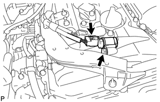
(b) Remove the bolt and oil control valve.
|
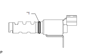
(c) Remove the O-ring from the oil control valve. Text in Illustration
|
|
3. REMOVE CAMSHAFT TIMING OIL CONTROL VALVE ASSEMBLY (for Intake Side)
|
(a) Disconnect the oil control valve connector. |
|
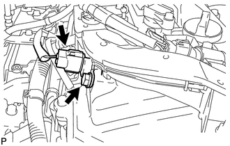
(b) Remove the bolt and oil control valve.
|
(c) Remove the O-ring from the oil control valve. Text in Illustration
|
|
 On-vehicle Inspection
ON-VEHICLE INSPECTION
PROCEDURE
1. INSPECT CAMSHAFT TIMING OIL CONTROL VALVE ASSEMBLY
(a) Connect the Techstream to the DLC3.
(b) Start the engine and turn the Techstream on.
(c) Inspect the oil ...
 Inspection
INSPECTION
CAUTION / NOTICE / HINT
HINT:
Use the same procedure for the intake side and exhaust side.
PROCEDURE
1. INSPECT CAMSHAFT TIMING OIL CONTROL VALVE ASSEMBLY
(a) Measure the r ...
Other materials about Toyota Venza:
Installation
INSTALLATION
CAUTION / NOTICE / HINT
HINT:
Use the same procedure for the LH side and RH side.
The following procedure listed is for the LH side.
PROCEDURE
1. INSTALL FRONT LOWER BALL JOINT
(a) Install the front lower ball jo ...
Engine oil
With the engine at operating temperature and turned off, check the oil level
on the dipstick.
- Checking the engine oil
Park the vehicle on level ground.
After warming up the engine and turning it off, wait more than five minutes for
the oil to ...
Ignition Hold Monitor Malfunction (B2271)
DESCRIPTION
This DTC is stored when a problem such as an open in the AM2 fuse, an open or
short in the wire harness between the fuse and power management control ECU, a short
in the IG output circuit inside the power management control ECU, a short betwee ...

0.1557