Toyota Venza: Amplifier Antenna
Components
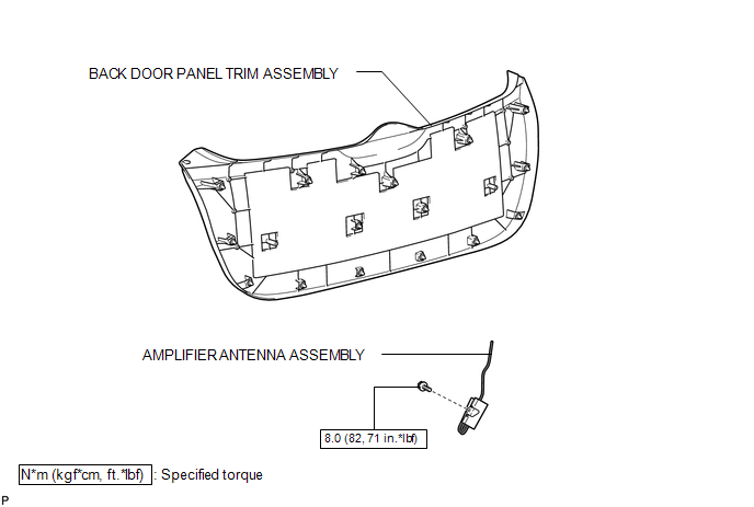
COMPONENTS
ILLUSTRATION
Removal
REMOVAL
PROCEDURE
1. REMOVE BACK DOOR PANEL TRIM ASSEMBLY
.gif)
2. REMOVE AMPLIFIER ANTENNA ASSEMBLY
|
(a) Disconnect the 2 connectors. |
|
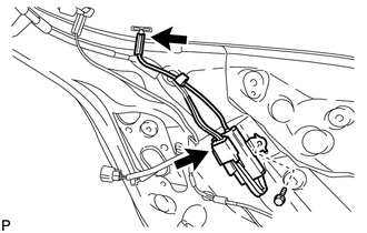
(b) Remove the bolt and amplifier antenna assembly.
Installation
INSTALLATION
PROCEDURE
1. INSTALL AMPLIFIER ANTENNA ASSEMBLY
|
(a) Install the amplifier antenna assembly with the bolt. Torque: 8.0 N·m {82 kgf·cm, 71 in·lbf} |
|
.png)
(b) Connect the 2 connectors.
2. INSTALL BACK DOOR PANEL TRIM ASSEMBLY
.gif)
 Audio / Video
...

Other materials about Toyota Venza:
Engine immobilizer system
The vehicle’s keys have built-in transponder chips that prevent the engine
from starting if the key has not been previously registered in the vehicle’s on-board
computer.
Never leave the keys inside the vehicle when you leave the vehicle.
Vehicles ...
Inspection
INSPECTION
PROCEDURE
1. INSPECT FUEL PUMP ASSEMBLY WITH FILTER
(a) Inspect fuel pump resistance.
(1) Measure the resistance according to the value(s) in the table below.
Standard Resistance:
Tester Connection
Condition
...
Inspection
INSPECTION
PROCEDURE
1. INSPECT TIE ROD ASSEMBLY LH
(a) Secure the tie rod assembly LH in a vise.
(b) Install the nut to the stud bolt.
(c) Flip the ball joint back and forth 5 times.
(d) Set a to ...

0.1162