Toyota Venza: Inspection
INSPECTION
PROCEDURE
1. INSPECT REAR SPEAKER ASSEMBLY
(a) With the speaker installed, check that there is no looseness or other abnormalities.
(b) Check that there is no foreign matter in the speaker, no tears on the speaker cone or other abnormalities.
|
(c) Measure the resistance of the speaker. Standard Resistance: for 6 Speakers:
If the result is not as specified, replace the speaker. Text in Illustration
|
|
.png)
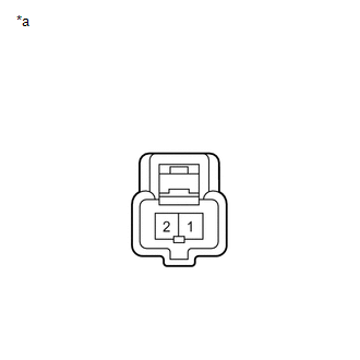
2. INSPECT REAR NO. 2 SPEAKER ASSEMBLY (for 13 Speakers)
(a) With the speaker installed, check that there is no looseness or other abnormalities.
(b) Check that there is no foreign matter in the speaker, no tears on the speaker cone or other abnormalities.
|
(c) Measure the resistance of the speaker. Standard Resistance:
If the result is not as specified, replace the speaker. Text in Illustration
|
|
 Removal
REMOVAL
PROCEDURE
1. DISCONNECT CABLE FROM NEGATIVE BATTERY TERMINAL
CAUTION:
Wait at least 90 seconds after disconnecting the cable from the negative (-)
battery terminal to disable the SRS sys ...
 Installation
INSTALLATION
PROCEDURE
1. INSTALL REAR NO. 2 SPEAKER ASSEMBLY (for 13 Speakers)
(a) Install the rear No. 2 speaker assembly with the 2 screws.
...
Other materials about Toyota Venza:
Theft Deterrent System Communication Line High Fixation (B279A)
DESCRIPTION
If the communication line (EFIO - IMI) to the certification ECU (smart key ECU
assembly) is stuck high output (e.g. shorted to +B), the ECM stores this DTC.
DTC No.
DTC Detection Condition
Trouble Area
...
Glossary Of Sae And Toyota Terms
GLOSSARY OF SAE AND TOYOTA TERMS
This glossary lists all SAE-J1930 terms and abbreviations used in this manual
in compliance with SAE recommendations, as well as their TOYOTA equivalents.
SAE
Abbreviation
SAE Term
TOYOTA ...
System Diagram
SYSTEM DIAGRAM
Communication Table
Sender
Receiver
Signal
Line
Main Body ECU
(Driver Side Junction Block Assembly)
Clearance Warning ECU Assembly
Destination information
...

0.1306