Toyota Venza: Removal
REMOVAL
PROCEDURE
1. DISCONNECT CABLE FROM NEGATIVE BATTERY TERMINAL
CAUTION:
Wait at least 90 seconds after disconnecting the cable from the negative (-)
battery terminal to disable the SRS system (See page
.gif) ).
).
NOTICE:
When disconnecting the cable, some systems need to be initialized after the cable
is reconnected (See page ).
2. REMOVE REAR DOOR INSIDE HANDLE BEZEL PLUG
3. REMOVE REAR POWER WINDOW REGULATOR SWITCH ASSEMBLY WITH REAR DOOR ARMREST BASE PANEL
4. REMOVE REAR DOOR TRIM BOARD SUB-ASSEMBLY
5. REMOVE REAR DOOR INNER GLASS WEATHERSTRIP
6. REMOVE REAR SPEAKER ASSEMBLY
|
(a) Disconnect the connector. |
|
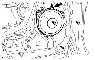
(b) Remove the 3 bolts and rear speaker assembly.
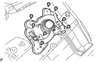
7. REMOVE REAR SPEAKER BRACKET (for 13 Speakers)
|
(a) Remove the 8 screws, rear speaker bracket and rear door speaker grille sub-assembly. |
|
8. REMOVE REAR NO. 2 SPEAKER ASSEMBLY (for 13 Speakers)
|
(a) Remove the 2 screws. |
|
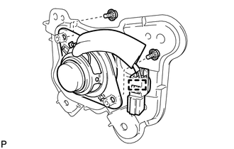
(b) Disengage the clamp and remove the rear No. 2 speaker assembly.
 Components
COMPONENTS
ILLUSTRATION
...
 Inspection
INSPECTION
PROCEDURE
1. INSPECT REAR SPEAKER ASSEMBLY
(a) With the speaker installed, check that there is no looseness or other abnormalities.
(b) Check that there is no foreign matter in the spea ...
Other materials about Toyota Venza:
Throttle Actuator Control Motor Current Range / Performance (P2118)
DESCRIPTION
The electronic throttle control system has a dedicated power supply circuit.
The voltage (+BM) is monitored and when it is low (below 4 V), the ECM determines
that there is a malfunction in the electronic throttle control system and cuts off
...
Evaporative Emission Control System Leak Detected (Gross Leak) (P0455,P0456)
DTC SUMMARY
DTC No.
Monitoring Item
Malfunction Detection Condition
Trouble Area
Detection Timing
Detection Logic
P0455
EVAP gross leak
Leak detection pum ...
Transmission Control Switch Circuit
DESCRIPTION
When the shift lever is in S and it is moved toward "-" or "+", it is possible
to select different shift ranges (1st through 6th ranges).
Moving the shift lever toward "+" increases the shift range by one, and movi ...

0.1748