Toyota Venza: Air Conditioning Amplifier Communication Stop Mode
DESCRIPTION
|
Detection Item |
Symptom |
Trouble Area |
|---|---|---|
|
Air Conditioning Amplifier Communication Stop Mode |
|
|
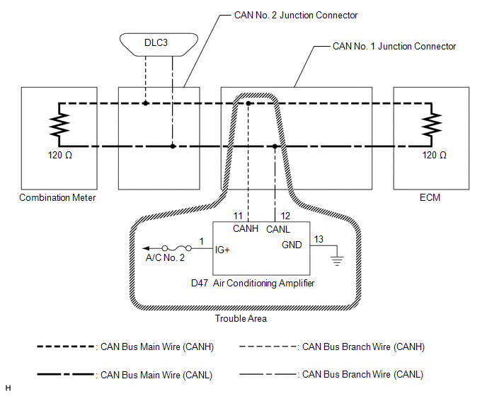
WIRING DIAGRAM
CAUTION / NOTICE / HINT
NOTICE:
- Turn the ignition switch off before measuring the resistances between CAN bus main wires and between CAN bus branch wires.
- Turn the ignition switch off before inspecting CAN bus wires for a ground short.
- After the ignition switch is turned off, check that the key reminder warning system and light reminder warning system are not operating.
- Before measuring the resistance, leave the vehicle as is for at least 1 minute and do not operate the ignition switch, any other switches or the doors. If any doors need to be opened in order to check connectors, open the doors and leave them open.
HINT:
- Operating the ignition switch, any other switches or a door triggers related ECU and sensor communication on the CAN. This communication will cause the resistance value to change.
- Even after DTCs are cleared, if a DTC is stored again after driving the vehicle for a while, the malfunction may be occurring due to vibration of the vehicle. In such a case, wiggling the ECUs or wire harness while performing the inspection below may help determine the cause of the malfunction.
PROCEDURE
|
1. |
CHECK CAN BUS WIRE FOR DISCONNECTION (AIR CONDITIONING AMPLIFIER BRANCH WIRE) |
(a) Turn the ignition switch off.
|
(b) Disconnect the connector of the air conditioning amplifier. Text in Illustration
|
|
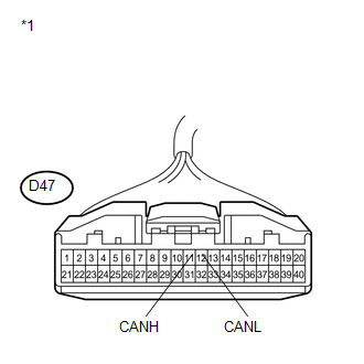
(c) Measure the resistance according to the value(s) in the table below.
Standard Resistance:
|
Tester Connection |
Switch Condition |
Specified Condition |
|---|---|---|
|
D47-11 (CANH) - D47-12 (CANL) |
Ignition switch off |
54 to 69 Ω |
| NG | .gif) |
REPAIR OR REPLACE CAN BUS BRANCH WIRE OR CONNECTOR (AIR CONDITIONING AMPLIFIER BRANCH WIRE) |
|
.gif)
|
2. |
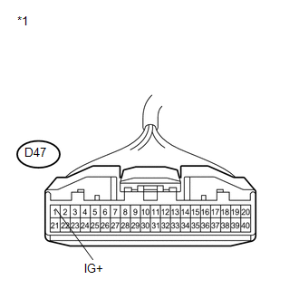
CHECK HARNESS AND CONNECTOR (POWER SOURCE TERMINAL) |
(a) Turn the ignition switch to ON.
|
(b) Measure the voltage according to the value(s) in the table below. Standard Voltage:
|
|
| NG | |
REPAIR OR REPLACE HARNESS OR CONNECTOR (POWER SOURCE CIRCUIT) |
|
|
3. |
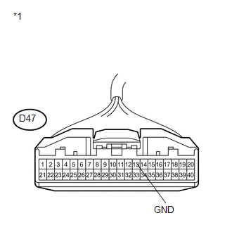
CHECK HARNESS AND CONNECTOR (GROUND TERMINAL) |
(a) Turn the ignition switch off.
|
(b) Measure the resistance according to the value(s) in the table below. Standard Resistance:
|
|
| OK | |
REPLACE AIR CONDITIONING AMPLIFIER |
| NG | |
REPAIR OR REPLACE HARNESS OR CONNECTOR (GROUND CIRCUIT) |
 Lost Communication with A/C ECU (U0164)
DESCRIPTION
DTC No.
DTC Detection Condition
Trouble Area
U0164
No communication from the air conditioning amplifier continues.
...
 Skid Control ECU Communication Stop Mode
DESCRIPTION
Detection Item
Symptom
Trouble Area
Skid Control ECU Communication Stop Mode
"ABS/VSC/TRAC" is not displa ...
Other materials about Toyota Venza:
Air Mix Damper Control Servo Motor Circuit (Passenger Side) (B1441/41)
DESCRIPTION
The air mix control servo motor sends pulse signals to indicate the damper position
to the A/C amplifier. The A/C amplifier activates the motor (normal or reverse)
based on these signals to move the air mix damper (front passenger side) to any ...
Detection range of the sensors
1. Approximately 1.6 ft. (50 cm)
2. Approximately 4.9 ft. (150 cm)
3. Approximately 2.0 ft. (60 cm)
The diagram shows the detection range of the sensors. Note that the sensors cannot
detect obstacles that are extremely close to the vehicle.
The range o ...
Catalyst System Efficiency Below Threshold (Bank 1) (P0420)
MONITOR DESCRIPTION
The ECM uses sensors mounted in front of and behind the Three-Way Catalytic Converter
(TWC) to monitor its efficiency.
The first sensor, the air fuel ratio sensor, sends pre-catalyst information to
the ECM. The second sensor, the heat ...

0.178