Toyota Venza: Inspection
INSPECTION
PROCEDURE
1. INSPECT THROTTLE BODY ASSEMBLY
 Text in Illustration
|
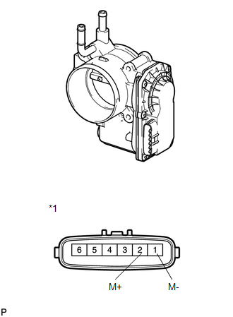
*1 |
Component without harness connected (Throttle Body) |
(a) Check that the throttle valve opens and closes smoothly.
(b) Check that there is no sludge accumulating around the throttle body.
(c) Measure the resistance according to the value(s) in the table below.
Standard Resistance:
|
Tester Connection |
Condition |
Specified Condition |
|---|---|---|
|
1 (M-) - 2 (M+) |
20°C (68°F) |
0.3 to 100 Ω |
If the result is not as specified, replace the throttle body assembly.
 On-vehicle Inspection
ON-VEHICLE INSPECTION
PROCEDURE
1. CHECK THROTTLE BODY ASSEMBLY
(a) Check the throttle control motor operating sounds.
(1) Turn the ignition switch to ON.
(2) When pressing the accelerator pedal, ...
 Removal
REMOVAL
PROCEDURE
1. REMOVE WINDSHIELD WIPER MOTOR AND LINK
(a) Remove the windshield wiper motor and link (See page
).
2. REMOVE OUTER COWL TOP PANEL SUB-ASSEMBLY
3. REMOVE NO. 1 ENGINE COV ...
Other materials about Toyota Venza:
Antenna location and effective range
- Antenna location
1. Antennas outside cabin
2. Antennas inside cabin
3. Antenna outside luggage compartment
- Effective range (areas within which the electronic key is detected)
When locking or unlocking the doors The system can be operat ...
Transmission Wire(when Not Using The Engine Support Bridge)
Components
COMPONENTS
ILLUSTRATION
Installation
INSTALLATION
PROCEDURE
1. INSTALL TRANSMISSION WIRE
(a) Coat the O-ring with ATF.
(b) Coat the bolt with ATF.
(c) Install the tr ...
Front seats
► Power seat
1. Seat position fore/aft control switch
2. Seatback angle control switch
3. Seat cushion (front) angle control switch (driver’s side only)
4. Vertical height control switch (driver’s side only)
5. Lumbar support control switch
& ...

0.1629