Toyota Venza: Removal
REMOVAL
CAUTION / NOTICE / HINT
HINT:
- Use the same procedure for the LH side and RH side.
- The following procedure is for the LH side.
- If the sensor rotor needs to be replaced, replace it together with the front drive shaft assembly.
PROCEDURE
1. DISCONNECT CABLE FROM NEGATIVE BATTERY TERMINAL
NOTICE:
When disconnecting the cable, some systems need to be initialized after the cable
is reconnected (See page .gif) ).
).
2. REMOVE FRONT WHEEL
3. REMOVE FRONT FENDER OUTSIDE MOULDING LH
4. REMOVE FRONT FENDER LINER LH
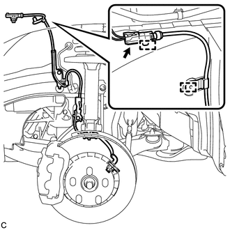
5. REMOVE FRONT SPEED SENSOR
|
(a) Disconnect the front speed sensor connector and remove the 2 clamps. |
|
|
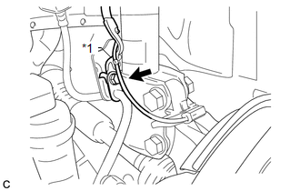
(b) Remove the bolt and No. 2 sensor clamp from the body. Text in Illustration
|
|
|
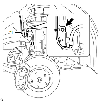
(c) Remove the bolt, No. 1 sensor clamp and flexible hose together from the shock absorber assembly. Text in Illustration
|
|
|
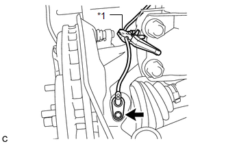
(d) Remove the bolt, resin clamp and front speed sensor. NOTICE:
|
|
 Components
COMPONENTS
ILLUSTRATION
ILLUSTRATION
...
 Installation
INSTALLATION
CAUTION / NOTICE / HINT
HINT:
Use the same procedure for the LH side and RH side.
The following procedure is for the LH side.
If the sensor rotor needs to be replaced, ...
Other materials about Toyota Venza:
Combination Meter ECU Communication Stop Mode
DESCRIPTION
Detection Item
Symptom
Trouble Area
Combination Meter ECU Communication Stop Mode
"Combination Meter" is not displayed on "CAN Bus Check" screen
of t ...
Installation
INSTALLATION
CAUTION / NOTICE / HINT
HINT:
Use the same procedure for the RH side and LH side.
The procedure listed below is for the LH side.
PROCEDURE
1. INSTALL REAR AIRBAG SENSOR
(a) Check that the ignition switch is off.
(b) Check ...
ECU Power Source Circuit
DESCRIPTION
This circuit provides power to operate the transponder key ECU assembly.
WIRING DIAGRAM
CAUTION / NOTICE / HINT
NOTICE:
If the transponder key ECU assembly is replaced, register the key and ECU communication
ID (See page ).
PROCEDURE
...

0.1722