Toyota Venza: Removal
REMOVAL
PROCEDURE
1. REMOVE WINDSHIELD WIPER MOTOR AND LINK
(a) Remove the windshield wiper motor and link (See page
.gif) ).
).
2. REMOVE OUTER COWL TOP PANEL SUB-ASSEMBLY
3. REMOVE NO. 1 ENGINE COVER SUB-ASSEMBLY
4. REMOVE COOL AIR INTAKE DUCT SEAL
5. REMOVE NO. 1 ENGINE UNDER COVER
6. REMOVE NO. 2 ENGINE UNDER COVER
7. DRAIN ENGINE COOLANT
8. REMOVE NO. 1 VACUUM SWITCHING VALVE ASSEMBLY
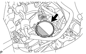
9. REMOVE AIR CLEANER CAP SUB-ASSEMBLY
|
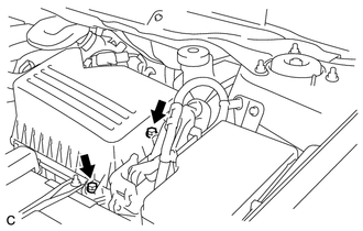
(a) Disconnect the mass air flow meter connector and separate the wire harness clamp from the air cleaner cap. |
|
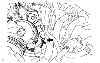
(b) Separate the hose from the hose clamp.
|
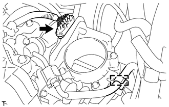
(c) Disconnect the ventilation hose from the cylinder head cover. |
|
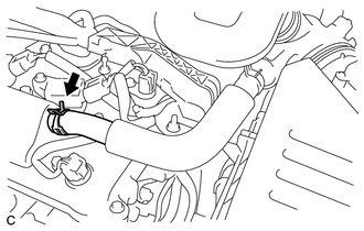
|
(d) Unlock the hose band and separate the air cleaner cap sub-assembly from the throttle body assembly. |
|
|
(e) Remove the 2 bolts and air cleaner cap sub-assembly. |
|
10. REMOVE THROTTLE BODY ASSEMBLY
|
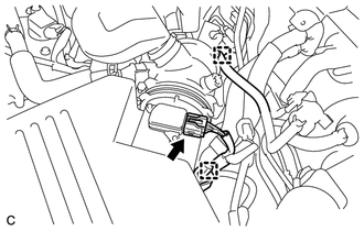
(a) Disconnect the throttle body assembly connector. |
|
(b) Disconnect the fuel tube from the clamp.
|
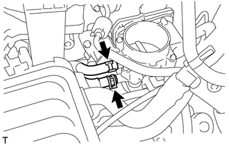
(c) Disconnect the 2 water by-pass hoses from the throttle body assembly. |
|
|
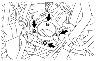
(d) Remove the 4 bolts and the throttle body assembly with the fuel tube bracket. |
|
|
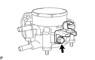
(e) Remove the bolt and fuel tube bracket. |
|
|
(f) Remove the gasket from the intake manifold. |
|
 Inspection
INSPECTION
PROCEDURE
1. INSPECT THROTTLE BODY ASSEMBLY
Text in Illustration
*1
Component without harness connected
(Throttle Body)
(a) Check that the throttle v ...
 Installation
INSTALLATION
PROCEDURE
1. INSTALL THROTTLE BODY ASSEMBLY
(a) Install a new gasket to the intake manifold.
(b) Install the fuel ...
Other materials about Toyota Venza:
Components
COMPONENTS
ILLUSTRATION
ILLUSTRATION
ILLUSTRATION
ILLUSTRATION
ILLUSTRATION
...
Transmitter Battery(w/o Smart Key System)
Replacement
REPLACEMENT
PROCEDURE
1. REMOVE TRANSMITTER HOUSING COVER
(a) Using a precision screwdriver with its tip wrapped in protective
tape, pry open the transmitter housing cover.
NOTICE:
Do not forcibly pry the cover.
HINT:
...
No Sound can be Heard from Speakers
PROCEDURE
1.
CHECK AUDIO SETTINGS
(a) In sound output setting mode, set volume, fader and balance to the initial
values and check that the sound is normal.
OK:
Audio system returns to normal.
HINT:
Sound quality adjustm ...

1.4911