Toyota Venza: Navigation Receiver Assembly Power Source Circuit
DESCRIPTION
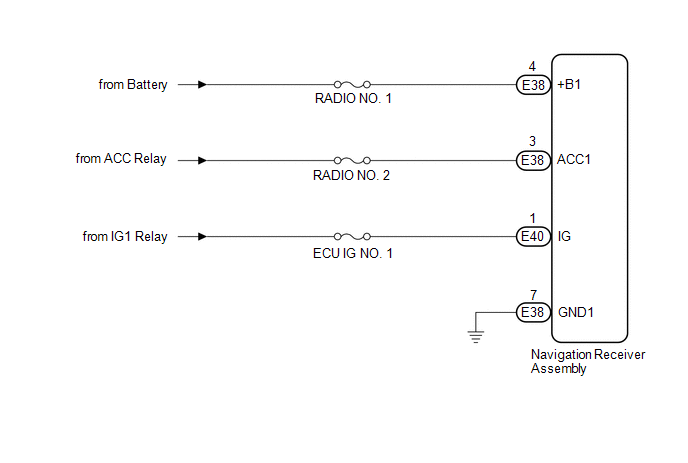
This is the power source circuit to operate the navigation receiver assembly.
WIRING DIAGRAM
CAUTION / NOTICE / HINT
NOTICE:
Inspect the fuses for circuits related to this system before performing the following inspection procedure.
PROCEDURE
|
1. |
CHECK HARNESS AND CONNECTOR (NAVIGATION RECEIVER ASSEMBLY POWER SOURCE) |
(a) Disconnect the E38 and E40 navigation receiver assembly connectors.
(b) Measure the resistance according to the value(s) in the table below.
Standard Resistance:
|
Tester Connection |
Condition |
Specified Condition |
|---|---|---|
|
E38-7 (GND1) - Body ground |
Always |
Below 1 Ω |
(c) Measure the voltage according to the value(s) in the table below.
Standard Voltage:
|
Tester Connection |
Condition |
Specified Condition |
|---|---|---|
|
E38-4 (+B1) - E38-7 (GND1) |
Always |
11 to 14 V |
|
E38-3 (ACC1) - E38-7 (GND1) |
Ignition switch ACC |
11 to 14 V |
|
E40-1 (IG) - E38-7 (GND1) |
Ignition switch ON |
11 to 14 V |
| OK | .gif) |
PROCEED TO NEXT SUSPECTED AREA SHOWN IN PROBLEM SYMPTOMS TABLE |
| NG | |
REPAIR OR REPLACE HARNESS OR CONNECTOR |
 Microphone Circuit between Microphone and Navigation Receiver Assembly
DESCRIPTION
The navigation receiver assembly and inner rear view mirror assembly
(amplifier microphone assembly) are connected to each other using the microphone
connection detection s ...

Other materials about Toyota Venza:
Vehicle Speed Sensor Malfunction (B2415)
DESCRIPTION
The AFS ECU (headlight swivel ECU assembly) receives signals indicating the front
right wheel speed from the skid control ECU using CAN communication.
DTC No.
DTC Detection Condition
Trouble Area
...
Removal
REMOVAL
PROCEDURE
1. DISCONNECT CABLE FROM NEGATIVE BATTERY TERMINAL
NOTICE:
When disconnecting the cable, some systems need to be initialized after the cable
is reconnected (See page ).
2. REMOVE NO. 1 ENGINE COVER SUB-ASSEMBLY
3. REMOVE COOL AIR ...
VSC OFF Indicator Light does not Come ON
DESCRIPTION
The skid control ECU is connected to the combination meter via CAN communication.
WIRING DIAGRAM
Refer to VSC OFF Indicator Light Remains ON (See page
).
PROCEDURE
1.
CHECK CAN COMMUNICATION SYSTEM
(a) Check ...

0.1138