Toyota Venza: Glove Box Light
Components
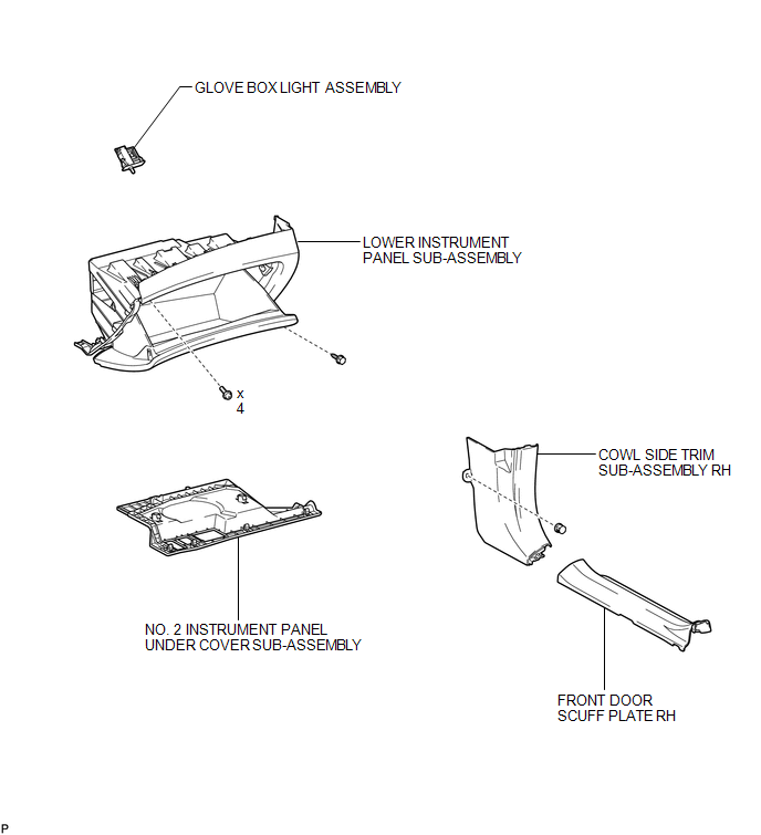
COMPONENTS
ILLUSTRATION
Inspection
INSPECTION
PROCEDURE
1. INSPECT GLOVE BOX LIGHT ASSEMBLY
|
(a) Connect a positive (+) lead from the battery to terminal 1 and a negative (-) lead to terminal 2. |
|
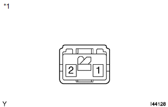
(b) Check that the light comes on when the glove box light switch is on (not pushed).
OK:
Glove box light comes on.
Text in Illustration|
*1 |
Component without harness connected (Glove Box Light Assembly) |
If the result is not as specified, replace the glove box light assembly.
Removal
REMOVAL
PROCEDURE
1. REMOVE FRONT DOOR SCUFF PLATE RH
HINT:
Use the same procedure for the RH side and LH side (See page
.gif) ).
).
2. REMOVE COWL SIDE TRIM SUB-ASSEMBLY RH
HINT:
Use the same procedure for the RH side and LH side (See page
).
3. REMOVE NO. 2 INSTRUMENT PANEL UNDER COVER SUB-ASSEMBLY
4. REMOVE LOWER INSTRUMENT PANEL SUB-ASSEMBLY
5. REMOVE GLOVE BOX LIGHT ASSEMBLY
|
(a) Disengage the 2 claws. |
|
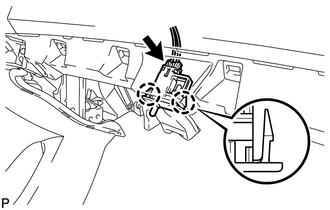
(b) Disconnect the connector and remove the glove box light assembly.
Installation
INSTALLATION
PROCEDURE
1. INSTALL GLOVE BOX LIGHT ASSEMBLY
|
(a) Connect the connector. |
|
.png)
(b) Engage the 2 claws to install the glove box light assembly.
2. INSTALL LOWER INSTRUMENT PANEL SUB-ASSEMBLY
.gif)
3. INSTALL NO. 2 INSTRUMENT PANEL UNDER COVER SUB-ASSEMBLY
4. INSTALL COWL SIDE TRIM SUB-ASSEMBLY RH
HINT:
Use the same procedure for the RH side and LH side (See page
).
5. INSTALL FRONT DOOR SCUFF PLATE RH
HINT:
Use the same procedure for the RH side and LH side (See page
).
 Front Door Courtesy Switch
Components
COMPONENTS
ILLUSTRATION
Inspection
INSPECTION
PROCEDURE
1. INSPECT COURTESY LIGHT SWITCH
(a) Measure the resistance according to the value(s) in the table below.
Standard Re ...
 Ignition Key Cylinder Light
Components
COMPONENTS
ILLUSTRATION
Inspection
INSPECTION
PROCEDURE
1. INSPECT TRANSPONDER KEY AMPLIFIER
(a) Connect a positive (+) lead from battery to terminal 2 and a negativ ...
Other materials about Toyota Venza:
Open or Short Circuit in ABS Motor Relay Circuit (C0273/13)
DESCRIPTION
The ABS motor relay supplies power to the ABS pump motor. While the ABS is activated,
the ECU turns the motor relay on and operates the ABS pump motor.
If the voltage supplied to the motor relay (+BM) is below the DTCs detection
threshold due ...
How To Proceed With Troubleshooting
CAUTION / NOTICE / HINT
HINT:
The wireless door lock control system troubleshooting procedures are
based on the premise that the power door lock control system is operating
normally. Check the power door lock control system first before troub ...
Rear Door LH ECU Communication Stop (B2324)
DESCRIPTION
This DTC is stored when LIN communication between the power window regulator
motor assembly (for rear LH side) and main body ECU (driver side junction block
assembly) stops for more than 10 seconds.
DTC No.
DTC Detection ...

0.1383