Toyota Venza: Front seats
► Power seat
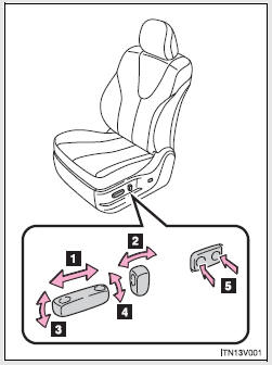
1. Seat position fore/aft control switch 2. Seatback angle control switch 3. Seat cushion (front) angle control switch (driver’s side only) 4. Vertical height control switch (driver’s side only) 5. Lumbar support control switch
► Manual seat
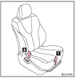
1. Seat position fore/aft adjustment lever 2. Seatback angle adjustment lever
Active head restraints
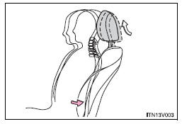
When the occupant’s lower back presses against the seatback during a rear-end collision, the head restraint moves slightly forward and upward to help reduce the risk of whiplash on the seat occupant.
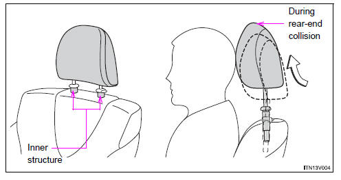
- Active head restraints
Even small forces applied to the seatback may cause the head restraint to move. Pushing up a locked head restraint forcibly may make the inner structure of the head restraint appear. This does not indicate a problem.
CAUTION
- Seat adjustment
• Be careful that the seat does not hit passengers or luggage.
• Do not recline the seat more than necessary when the vehicle is in motion to reduce the risk of sliding under the lap belt.
If the seat is too reclined, during an accident the lap belt may slide past the hips and apply restraint forces directly to the abdomen or your neck may contact the shoulder belt, increasing the risk of death or serious injury.
• Manual seat only: After adjusting the seat, make sure that the seat is locked in position.

 Rear seats
Seatback angle adjustment lever
Pull up the lever until the lock is completely released.
Folding down the rear seatbacks
- Before folding down the rear seatbacks
Stow the seat belt buckl ...
Other materials about Toyota Venza:
Starter Signal Circuit
DESCRIPTION
1. w/o Smart Key System
While the engine is being cranked, current flows from terminal ST1 of the ignition
switch assembly to the park/neutral position switch assembly and also flows to terminal
STA of the ECM (STA Signal).
2. w/ Smart Key S ...
Lost Communication with "Door Control Module A" (U0199)
DESCRIPTION
DTC No.
DTC Detection Condition
Trouble Area
U0199
No communication from the outer mirror control ECU (for front passenger
side) continues.
Outer mirror control ...
Test Mode Procedure
TEST MODE PROCEDURE
1. DESCRIPTION
HINT:
When using a chassis dynamometer, brake tester, etc. to perform a vehicle test,
activate test mode to avoid a "different tire diameter installed" incorrect judgment.
Test mode does not have a AWD paramet ...

0.1323