Toyota Venza: Clearance Warning ECU Power Source Circuit
DESCRIPTION
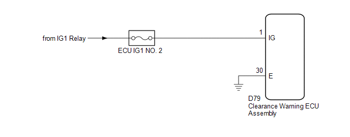
This circuit provides power to operate the clearance warning ECU assembly.
WIRING DIAGRAM
CAUTION / NOTICE / HINT
NOTICE:
Inspect the fuses for circuits related to this system before performing the following inspection procedure.
PROCEDURE
|
1. |
CHECK HARNESS AND CONNECTOR (CLEARANCE WARNING ECU ASSEMBLY POWER SOURCE) |
(a) Disconnect the D79 clearance warning ECU assembly connector.
(b) Measure the voltage according to the value(s) is the table below.
Standard Voltage:
|
Tester Connection |
Condition |
Specified Condition |
|---|---|---|
|
D79-1 (IG) - Body ground |
Engine switch on (IG) |
11 to 14 V |
|
D79-1 (IG) - Body ground |
Engine switch off |
Below 1 V |
| NG | .gif) |
REPAIR OR REPLACE HARNESS OR CONNECTOR |
|
.gif)
|
2. |
CHECK HARNESS AND CONNECTOR (CLEARANCE WARNING ECU ASSEMBLY - BODY GROUND) |
(a) Measure the resistance according to the value(s) in the table below.
Standard Resistance:
|
Tester Connection |
Condition |
Specified Condition |
|---|---|---|
|
D79-30 (E) - Body ground |
Always |
Below 1 Ω |
| OK | |
PROCEED TO NEXT SUSPECTED AREA SHOWN IN PROBLEM SYMPTOMS TABLE |
| NG | |
REPAIR OR REPLACE HARNESS OR CONNECTOR |
 Clearance Warning Buzzer Circuit
DESCRIPTION
This circuit consists of the No. 1 clearance warning buzzer and clearance warning
ECU assembly. An ECU-excited type buzzer is used. The ECU operates the buzzer using
a sound pattern t ...

Other materials about Toyota Venza:
Components
COMPONENTS
ILLUSTRATION
ILLUSTRATION
ILLUSTRATION
ILLUSTRATION
ILLUSTRATION
ILLUSTRATION
ILLUSTRATION
ILLUSTRATION
ILLUSTRATION
...
Portable Player cannot be Connected Manually/Automatically
CAUTION / NOTICE / HINT
HINT:
Some versions of "Bluetooth" compatible audio players may not function properly,
or the functions may be limited using the radio and display receiver assembly, even
if the portable audio player itself can play file ...
Removal
REMOVAL
PROCEDURE
1. REMOVE FRONT DOOR SCUFF PLATE LH
2. REMOVE COWL SIDE TRIM SUB-ASSEMBLY LH
3. REMOVE LOWER NO. 1 INSTRUMENT PANEL FINISH PANEL
4. REMOVE OUTER MIRROR SWITCH ASSEMBLY
(a) Disengage the 2 claws and remove the outer m ...

0.1695