Toyota Venza: Front Door Courtesy Switch
Components
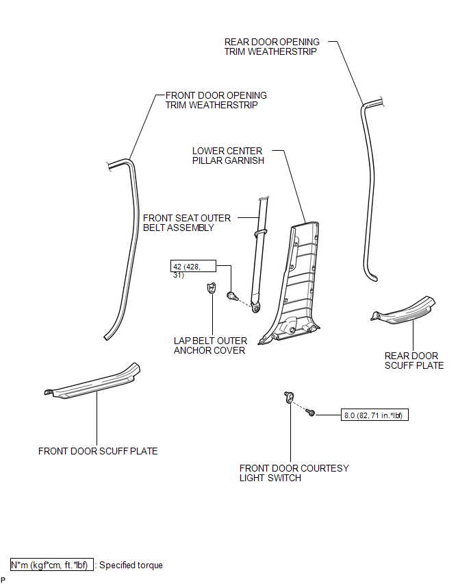
COMPONENTS
ILLUSTRATION
Inspection
INSPECTION
PROCEDURE
1. INSPECT COURTESY LIGHT SWITCH
(a) Measure the resistance according to the value(s) in the table below.
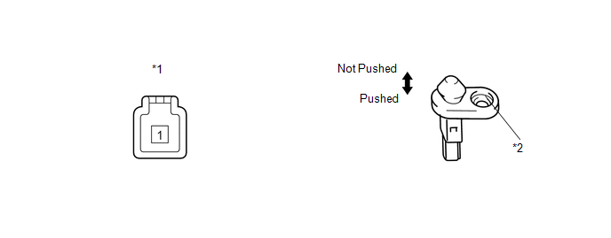
Standard Resistance:
|
Tester Connection |
Switch Condition |
Specified Condition |
|---|---|---|
|
1 - Switch body |
Pushed |
10 kΩ or higher |
|
1 - Switch body |
Not pushed |
Below 1 Ω |
|
*1 |
Component without harness connected (Courtesy Light Switch) |
*2 |
Switch Body |
If the result is not as specified, replace the courtesy light switch.
Removal
REMOVAL
PROCEDURE
1. REMOVE FRONT DOOR SCUFF PLATE
.gif)
2. DISCONNECT FRONT DOOR OPENING TRIM WEATHERSTRIP
3. REMOVE REAR DOOR SCUFF PLATE
4. DISCONNECT REAR DOOR OPENING TRIM WEATHERSTRIP
5. REMOVE LAP BELT OUTER ANCHOR COVER
6. DISCONNECT FRONT SEAT OUTER BELT ASSEMBLY
7. REMOVE LOWER CENTER PILLAR GARNISH
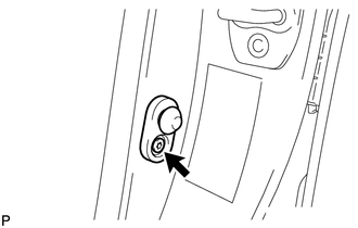
8. REMOVE FRONT DOOR COURTESY LIGHT SWITCH
(a) Disconnect the connector.
|
(b) Using "TORX" socket wrench T30, remove the "TORX" bolt and front door courtesy light switch. |
|
Installation
INSTALLATION
PROCEDURE
1. INSTALL FRONT DOOR COURTESY LIGHT SWITCH
|
(a) Using "TORX" socket wrench T30, install the front door courtesy light switch with the "TORX" bolt. Torque: 8.0 N·m {82 kgf·cm, 71 in·lbf} |
|
.png)
(b) Connect the connector.
2. INSTALL LOWER CENTER PILLAR GARNISH
.gif)
3. CONNECT FRONT SEAT OUTER BELT ASSEMBLY
4. INSTALL LAP BELT OUTER ANCHOR COVER
5. CONNECT REAR DOOR OPENING TRIM WEATHERSTRIP
6. INSTALL REAR DOOR SCUFF PLATE
7. CONNECT FRONT DOOR OPENING TRIM WEATHERSTRIP
8. INSTALL FRONT DOOR SCUFF PLATE
 Door Courtesy Light
Components
COMPONENTS
ILLUSTRATION
Removal
REMOVAL
PROCEDURE
1. REMOVE COURTESY LIGHT ASSEMBLY
(a) Using a screwdriver wrapped with protective tape, disengage the claw.
Text ...
 Glove Box Light
Components
COMPONENTS
ILLUSTRATION
Inspection
INSPECTION
PROCEDURE
1. INSPECT GLOVE BOX LIGHT ASSEMBLY
(a) Connect a positive (+) lead from the battery to terminal 1 and a
...
Other materials about Toyota Venza:
Operation Check
OPERATION CHECK
1. CHECK POWER SEAT FUNCTION
(a) Check the basic functions.
(1) Operate the power seat switches and check to make sure each seat function
work:
Sliding
Front vertical (Driver side only)
Lumbar support
Lifter (Driver s ...
Motor Circuit Malfunction (C1521,C1531-C1534,C1554)
DESCRIPTION
If the power steering ECU detects these DTCs, it will shut off the motor relay
circuit (built into the power steering ECU) and stop power assist. However, power
assist continues if DTC C1533 or C1534 is stored.
DTC No.
D ...
Illumination for Panel Switch does not Come on with Tail Switch ON
PROCEDURE
1.
CHECK VEHICLE SIGNAL (OPERATION CHECK)
(a) Enter the "Vehicle Signal Check Mode" screen. Refer to Check Vehicle Signal
in Operation Check (See page ).
(b) Check that the display changes between ON ...

0.1463