Toyota Venza: Ignition Key Cylinder Light
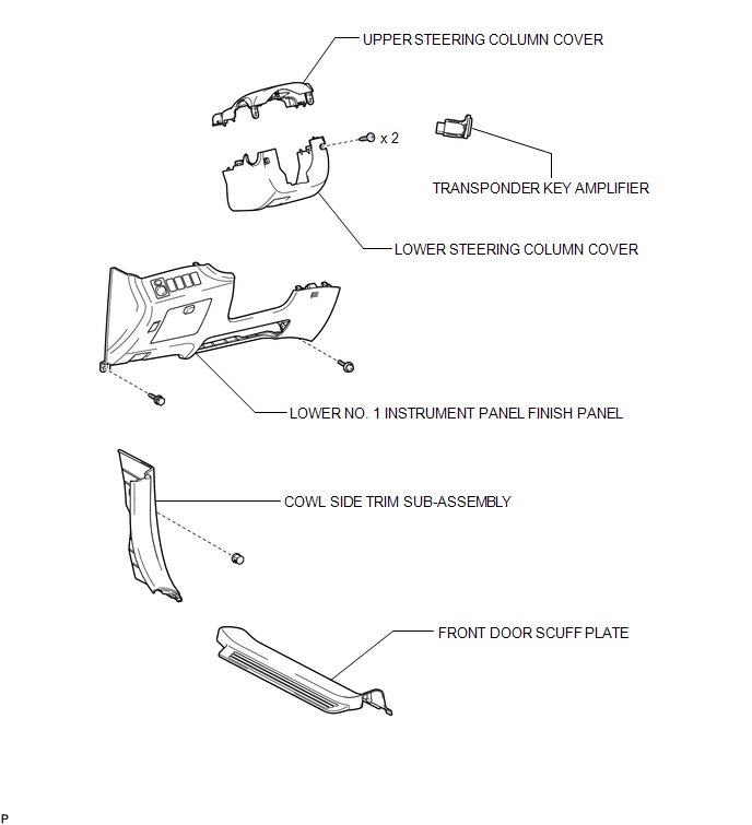
Components
COMPONENTS
ILLUSTRATION
Inspection
INSPECTION
PROCEDURE
1. INSPECT TRANSPONDER KEY AMPLIFIER
|
(a) Connect a positive (+) lead from battery to terminal 2 and a negative (-) lead to terminal 6. |
|
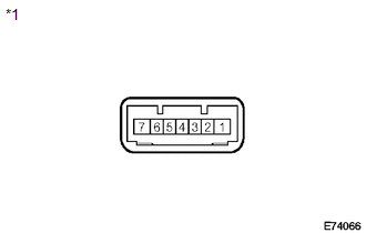
(b) Check that the light comes on.
OK:
The light comes on.
Text in Illustration|
*1 |
Component without harness connected (transponder key amplifier) |
If the result is not as specified, replace the transponder key amplifier.
Removal
REMOVAL
PROCEDURE
1. REMOVE FRONT DOOR SCUFF PLATE
.gif)
2. REMOVE COWL SIDE TRIM SUB-ASSEMBLY
3. REMOVE LOWER NO. 1 INSTRUMENT PANEL FINISH PANEL
4. REMOVE LOWER STEERING COLUMN COVER
5. REMOVE UPPER STEERING COLUMN COVER
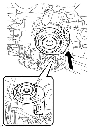
6. REMOVE TRANSPONDER KEY AMPLIFIER
|
(a) Disengage the 2 claws and disconnect the transponder key amplifier as shown in the illustration. |
|
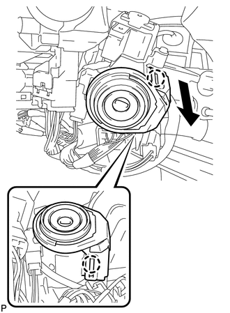
|
(b) Disconnect the connector and remove the transponder key amplifier. |
|
Installation
INSTALLATION
PROCEDURE
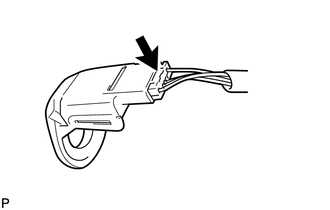
1. INSTALL TRANSPONDER KEY AMPLIFIER
|
(a) Connect the connector to the transponder key amplifier. |
|
.png)
|
(b) Engage the 2 claws and install the transponder key amplifier. |
|
2. INSTALL UPPER STEERING COLUMN COVER
.gif)
3. INSTALL LOWER STEERING COLUMN COVER
4. INSTALL LOWER NO. 1 INSTRUMENT PANEL FINISH PANEL
5. INSTALL COWL SIDE TRIM SUB-ASSEMBLY
6. INSTALL FRONT DOOR SCUFF PLATE
 Glove Box Light
Components
COMPONENTS
ILLUSTRATION
Inspection
INSPECTION
PROCEDURE
1. INSPECT GLOVE BOX LIGHT ASSEMBLY
(a) Connect a positive (+) lead from the battery to terminal 1 and a
...
 Lighting System
...
Other materials about Toyota Venza:
Registration
REGISTRATION
PROCEDURE
1. DESCRIPTION OF CODE REGISTRATION
It is necessary to register the transmitter IDs in the tire pressure warning
ECU when replacing a tire pressure warning valve and transmitter and/or a tire pressure
warning ECU.
Prepare all tra ...
On-vehicle Inspection
ON-VEHICLE INSPECTION
PROCEDURE
1. INSPECT PARK/NEUTRAL POSITION SWITCH ASSEMBLY OPERATION
(a) Apply the parking brake.
(b) Turn the ignition switch to ON.
(c) Depress the brake pedal and check that the engine starts when the shift lever
is in N or P, b ...
Inspection
INSPECTION
PROCEDURE
1. INSPECT EVAPORATOR TEMPERATURE SENSOR
(a) Measure the resistance according to the value(s) in the table below.
Standard Resistance:
Tester Connection
Condition
Specified Condition
...

0.1688