Toyota Venza: Engine Speed Signal Error (Test Mode DTC) (C2194/94)
DESCRIPTION
The tire pressure warning ECU receives an engine speed signal from the ECM. This DTC is stored upon entering signal check mode (test mode), and cleared when an engine speed signal of 1000 rpm is detected for 3 seconds or more. This DTC is output only in signal check mode.
|
DTC No. |
DTC Detection Condition |
Trouble Area |
|---|---|---|
|
C2194/94 |
Test mode procedure is performed |
|
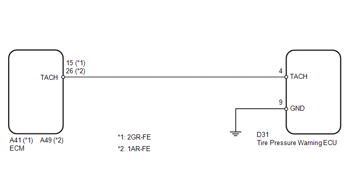
WIRING DIAGRAM
CAUTION / NOTICE / HINT
NOTICE:
- When replacing the tire pressure warning ECU, read the transmitter IDs stored in the old ECU using the Techstream and write them down before removal.
- It is necessary to perform registration (See page
.gif) ) of the transmitter IDs into the tire
) of the transmitter IDs into the tire
pressure warning ECU if the ECU has been replaced.
PROCEDURE
|
1. |
READ VALUE USING TECHSTREAM (ENGINE SPEED) |
(a) Turn the ignition switch off.
(b) Connect the Techstream to the DLC3.
(c) Turn the ignition switch to ON.
(d) Turn the Techstream on.
(e) Enter the following menus: Chassis / Tire Pressure Monitor / Data List.
(f) Check that the values indicated on the Techstream and on the combination meter are the same.
Tire Pressure Monitor|
Tester Display |
Measurement Item/Range |
Normal Condition |
Diagnostic Note |
|---|---|---|---|
|
Engine Speed |
Engine speed/ min.: 0 rpm max.: 65535 rpm |
Almost same as actual engine speed |
Speed indicated on combination meter |
OK:
Engine speed indicated on the Techstream and on the combination meter are the same.
| OK | .gif) |
USE SIMULATION METHOD TO CHECK |
|
.gif)
|
2. |
INSPECT TIRE PRESSURE WARNING ECU (TACH SIGNAL) |
|
(a) Disconnect the D31 ECU connector. |
|
(b) Start the engine.
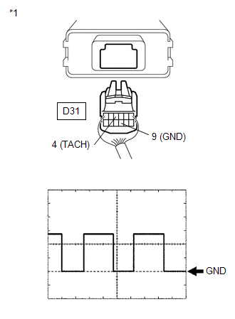
(c) Check the waveform of the ECU connector using an oscilloscope while idling the engine.
OK:
|
Tester Connection |
Condition |
Specified Condition |
|---|---|---|
|
D31-4 (TACH) - D31-9 (GND) |
Idling |
Correct waveform appears as shown |
|
*1 |
Rear view of wire harness connector (to Tire Pressure Warning ECU) |
|
Item |
Contents |
|---|---|
|
Tool Setting |
5 V/DIV., 10 ms/DIV. |
HINT:
The wavelength becomes shorter as the engine speed increases.
| OK | |
REPLACE TIRE PRESSURE WARNING ECU |
|
|
3. |
CHECK HARNESS AND CONNECTOR (TIRE PRESSURE WARNING ECU - ECM) |
|
(a) Disconnect the D31 ECU connector. |
|
(b) Disconnect the A41 or A49 ECM connector.
(c) Measure the resistance according to the value(s) in the table below.
Standard Resistance:
|
Tester Connection |
Condition |
Specified Condition |
|---|---|---|
|
D31-4 (TACH) - A41-15 (TACH) |
Always |
Below 1 Ω |
|
D31-4 (TACH) - A49-26 (TACH) |
Always |
Below 1 Ω |
|
D31-4 (TACH) - Body ground |
Always |
10 kΩ or higher |
|
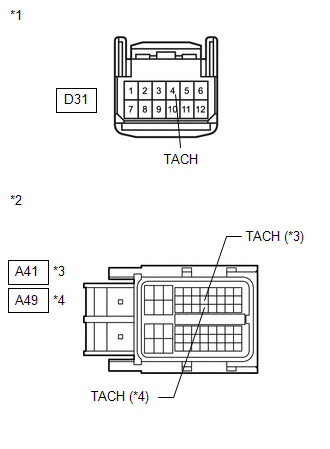
*1 |
Front view of wire harness connector (to Tire Pressure Warning ECU) |
|
*2 |
Front view of wire harness connector (to ECM) |
|
*3 |
2GR-FE |
|
*4 |
1AR-FE |
|
Result |
Proceed to |
|---|---|
|
OK (for 2GR-FE) |
A |
|
OK (for 1AR-FE) |
B |
|
NG |
C |
| A | |
REPLACE ECM (for 2GR-FE) |
| B | |
REPLACE ECM (for 1AR-FE) |
| C | |
REPAIR OR REPLACE HARNESS OR CONNECTOR |
 Transmitter ID not Received in Main Mode (C2126/26)
DESCRIPTION
After all IDs are registered, DTC C2126/26 is set in the tire pressure warning
ECU and the tire pressure warning light blinks for 1 minute and then comes on.
When the tire pressure war ...
 No Signal from Transmitter ID1 (C2121/21-C2124/24,C2181/81-C2184/84)
DESCRIPTION
The tire pressure warning valve and transmitter installed in each tire and wheel
assembly measures the tire pressures. The measured values are transmitted as radio
waves to the tire p ...
Other materials about Toyota Venza:
Dtc Check / Clear
DTC CHECK / CLEAR
1. CHECK DTC
(a) Connect the Techstream to the DLC3.
(b) Turn the ignition switch to ON.
(c) Turn the Techstream on.
(d) Enter the following menus: Body Electrical / Driver Seat / Trouble Codes.
(e) Check for DTCs (See page ).
2. CLEA ...
Terminals Of Ecu
TERMINALS OF ECU
1. CHECK POWER MANAGEMENT CONTROL ECU
(a) Disconnect the D42 and D43 connectors.
(b) Measure the voltage and resistance according to the value(s) in the table
below.
Tester Connection
Wiring Color
Termi ...
Removal
REMOVAL
CAUTION / NOTICE / HINT
NOTICE:
Release the vacuum from the booster by depressing the brake pedal several times.
Then remove the brake master cylinder from the brake booster.
PROCEDURE
1. DRAIN BRAKE FLUID
NOTICE:
If brake fluid leaks onto any ...

0.1749