Toyota Venza: Brake Switch "B" Circuit High (P0724)
DESCRIPTION
The purpose of this circuit is to prevent the engine from stalling when the brakes are suddenly applied while driving in the lock-up condition.
When the brake pedal is depressed, this switch sends a signal to the TCM. Then the TCM cancels the operation of the lock-up clutch while braking is in progress.
|
DTC No. |
DTC Detection Condition |
Trouble Area |
|---|---|---|
|
P0724 |
The stop light switch remains ON even when the vehicle is driven in a STOP (less than 3 km/h (2 mph)) and GO (30 km/h (19 mph) or more) fashion 5 times. (2-trip detection logic). |
|
MONITOR DESCRIPTION
This DTC indicates that the stop light switch remains ON. When the stop light switch remains ON during "stop and go" driving, the TCM interprets this as a fault in the stop light switch, illuminates the MIL, and stores the DTC. The vehicle must stop (less than 3 km/h (2 mph)) and go (30 km/h (19 mph) or more) five times for two consecutive driving cycles in order to set this DTC.
MONITOR STRATEGY
|
Related DTCs |
P0724: Stop light switch/Range check/Rationality |
|
Required sensors/Components |
Stop light switch |
|
Frequency of operation |
Continuous |
|
Duration |
GO and STOP 5 times |
|
MIL operation |
2 driving cycles |
|
Sequence of operation |
None |
TYPICAL ENABLING CONDITIONS
The stop light switch remains ON during GO and STOP 5 times. GO and STOP are defined as follows;|
The monitor will run whenever this DTC is not present. |
None |
|
GO: (Vehicle speed is 18.63 mph (30 km/h) or more) |
18.65 mph (30 km/h) or more |
|
STOP: (Vehicle speed is less than 1.86 mph (3 km/h)) |
Less than 1.86 mph (3 km/h) |
|
Starter |
OFF |
|
Battery voltage |
8 V or more |
|
Ignition switch |
ON |
TYPICAL MALFUNCTION THRESHOLDS
|
Brake switch |
Remains ON |
WIRING DIAGRAM

CAUTION / NOTICE / HINT
NOTICE:
Perform the universal trip to clear permanent DTCs (See page
.gif) ).
).
PROCEDURE
|
1. |
READ VALUE USING DATA LIST (STP SIGNAL) |
HINT:
Using the Techstream to read the Data List allows the values or states of switches, sensors, actuators and other items to be read without removing any parts. This non-intrusive inspection can be very useful because intermittent conditions or signals may be discovered before parts or wiring is disturbed. Reading the Data List information early in troubleshooting is one way to save diagnostic time.
NOTICE:
In the table below, the values listed under "Normal Condition" are reference values. Do not depend solely on these reference values when deciding whether a part is faulty or not.
(a) Turn the ignition switch off.
(b) Connect the Techstream to the DLC3.
(c) Turn the ignition switch to ON.
(d) Turn the Techstream on.
(e) Enter the following menus: Powertrain / ECT / Data List.
(f) According to the display on the Techstream, read the Data List.
Standard:
|
Item |
Measurement Item/ Range (display) |
Normal Condition |
|---|---|---|
|
Stop Light Switch |
Stop light switch status/ ON or OFF |
|
NOTICE:
In the table above, the conditions listed under "Normal Condition" are reference conditions. Do not depend solely on these reference conditions when deciding whether a part is faulty.
| OK | .gif) |
CHECK FOR INTERMITTENT PROBLEMS |
|
.gif)
|
2. |
CHECK STOP LIGHT SWITCH ASSEMBLY INSTALLATION |
(a) Check the stop light switch assembly installation (See page
).
OK:
Stop light switch assembly is installed correctly.
| NG | |
SECURELY REINSTALL STOP LIGHT SWITCH ASSEMBLY |
|
|
3. |
INSPECT STOP LIGHT SWITCH ASSEMBLY |
|
(a) Remove the stop light switch assembly. |
|
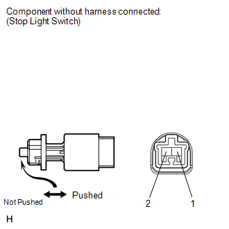
(b) Measure the resistance according to the value(s) in the table below.
Standard Resistance:
|
Tester Connection |
Switch Condition |
Specified Condition |
|---|---|---|
|
1 - 2 |
Pin not pushed |
Below 1 Ω |
|
3 - 4 |
Pin pushed |
Below 1 Ω |
|
1 - 2 |
Pin pushed |
10 kΩ or higher |
|
3 - 4 |
Pin not pushed |
10 kΩ or higher |
| NG | |
REPLACE STOP LIGHT SWITCH ASSEMBLY |
|
|
4. |
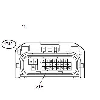
CHECK HARNESS AND CONNECTOR (STOP LIGHT SWITCH ASSEMBLY - TCM) |
|
(a) Install the stop light switch assembly. |
|
(b) Connect the stop light switch connector.
(c) Disconnect the TCM connector.
(d) Measure the voltage according to the value(s) in the table below when the brake pedal is depressed and released.
Standard Voltage:
|
Tester Connection |
Condition |
Specified Condition |
|---|---|---|
|
B40-12 (STP) - Body ground |
Brake pedal is depressed |
7.5 to 14 V |
|
B40-12 (STP) - Body ground |
Brake pedal is released |
Below 1 V |
|
*1 |
Front view of wire harness connector (to TCM) |
| OK | |
REPLACE TCM |
| NG | |
REPAIR OR REPLACE HARNESS OR CONNECTOR |
 Pressure Control Solenoid "A" Performance (Shift Solenoid Valve SL1) (P0746)
SYSTEM DESCRIPTION
The TCM uses the vehicle speed signal and signals from the transmission speed
sensors (NC, NT) to detect the actual gear (1st, 2nd, 3rd, 4th, 5th or 6th gear).
Then the TCM comp ...
 Torque Converter Clutch Solenoid Performance (Shift Solenoid Valve SL) (P0741)
SYSTEM DESCRIPTION
The TCM uses signals from the throttle position sensor, air-flow meter, turbine
(input) speed sensor, intermediate (counter gear) speed sensor and crankshaft position
sensor to ...
Other materials about Toyota Venza:
Installation
INSTALLATION
PROCEDURE
1. INSTALL AIR CONDITIONING UNIT ASSEMBLY
(a) Install the air conditioning unit assembly with the 3 nuts.
Torque:
9.8 N·m {100 kgf·cm, 87 in·lbf}
NOTICE:
Tighten the nuts in the order shown in the illustration to install the ...
Intermediate Shaft Speed Sensor "A" Circuit (P0791,P0793)
DESCRIPTION
This sensor detects the rotation speed of the counter gear which shows the output
speed of transaxle. By comparing the input turbine speed signal (NT) with the counter
gear speed sensor signal (NC), the TCM detects the shift timing of the gear ...
Removal
REMOVAL
PROCEDURE
1. DISCONNECT CABLE FROM NEGATIVE BATTERY TERMINAL
CAUTION:
Wait at least 90 seconds after disconnecting the cable from the negative (-)
battery terminal to disable the SRS system.
NOTICE:
When disconnecting the cable, some systems ne ...

0.1525