Toyota Venza: No Signal from Transmitter ID1 (C2121/21-C2124/24,C2181/81-C2184/84)
DESCRIPTION
The tire pressure warning valve and transmitter installed in each tire and wheel assembly measures the tire pressures. The measured values are transmitted as radio waves to the tire pressure warning antenna and receiver on the body and then sent to the tire pressure warning ECU. The ECU compares the measured air pressure values with the air pressure threshold. When the measured air pressure value is less than this threshold, the warning light in the accessory meter comes on.
The tire pressure warning valve and transmitters constantly send radio waves to the tire pressure warning antenna and receiver.
Under the conditions below, the tire pressure warning antenna and receiver is unable to receive the signals from the tire pressure warning valve and transmitters, and a DTC is stored.
- Facilities or devices that use similar radio frequencies are located in the vicinity of the vehicle.
- Devices using similar radio frequencies are used in the vehicle.
- The tire pressure warning valve and transmitter ID is mistyped during registration.
- A wheel from a different vehicle is installed.
HINT:
When a transmitter ID is not received from a tire pressure warning valve and transmitter for a total of 20 minutes while the vehicle speed is over 8 km/h (5 mph) or no transmitter ID is received from all of the tire pressure warning valve and transmitters for a total of 20 minutes, DTCs are set.
DTCs from C2121/21 to C2124/24 can only be cleared by using the Techstream. DTCs from C2181/81 to C2184/84 can be cleared when the transmitter in the tire pressure warning valve and transmitter sends a forced transmission signal or signal check mode (test mode) ends. DTCs from C2181/81 to C2184/84 are output only in signal check (test mode).
|
DTC No. |
DTC Detection Condition |
Trouble Area |
|---|---|---|
|
C2121/21 C2122/22 C2123/23 C2124/24 |
When the following conditions is met: (a) When all conditions below are met:
(b) When all of the following conditions are met:
|
|
|
C2181/81 C2182/82 C2183/83 C2184/84 |
Test mode procedure is performed. |
|
NOTICE:
When DTCs C2121/21 to C2124/24 are set, DTC C2173/73 may be set simultaneously. In such cases, troubleshoot C2173/73 first, then troubleshoot DTCs C2121/21 to C2124/24.
HINT:
It is necessary to perform this procedure to identify the malfunctioning tire pressure warning valve and transmitter as it cannot be identified only by the output DTC.
WIRING DIAGRAM
.png)
CAUTION / NOTICE / HINT
NOTICE:
- When replacing the tire pressure warning ECU, read the transmitter IDs stored in the old ECU using the Techstream and write them down before removal.
- It is necessary to perform registration (See page
.gif) ) of the transmitter IDs into the tire
) of the transmitter IDs into the tire
pressure warning ECU if the ECU and/or any of the valve and transmitters have been replaced.
PROCEDURE
|
1. |
READ OUTPUT DTC (DTC C2173/73) |
(a) Turn the ignition switch off.
(b) Connect the Techstream to the DLC3.
(c) Turn the ignition switch to ON.
(d) Turn the Techstream on.
(e) Enter the following menus: Chassis / Tire Pressure Monitor / Trouble Codes.
(f) Read DTCs.
|
Result |
Proceed to |
|---|---|
|
DTC C2173/73 is not output |
A |
|
DTC C2173/73 is output |
B |
NOTICE:
When DTC C2173/73 is output, troubleshoot that DTC first. Then troubleshoot DTCs C2121/21 to C2124/24.
| B | .gif) |
GO TO DTC C2173/73 |
|
.gif)
|
2. |
CHECK FREQUENCY RECEIVING CONDITION |
(a) Check that the vehicle is not located in an area such as described below:
(1) Facilities or devices that use similar radio frequencies are located in the vicinity of the vehicle.
HINT:
If the vehicle is located in an area described above, the tire pressure warning light may come on only in a particular area due to interfering radio frequencies.
(2) Devices using similar radio frequencies are used in the vehicle.
OK:
Facilities, or devices that use similar radio frequencies are not located in the vicinity of the vehicle.
HINT:
Radio transmissions may be interrupted due to the surroundings or devices installed by the user.
| NG | |
CHECK IF ANY DEVICE IS INSTALLED BY USER |
|
|
3. |
IDENTIFY TRANSMITTER CORRESPONDING TO DTC |
(a) Set all tire pressures to the specified value(s) (See page
).
(b) Turn the ignition switch off.
(c) Connect the Techstream to the DLC3.
(d) Turn the ignition switch to ON.
(e) Turn the Techstream on.
(f) Enter the following menus: Chassis / Tire Pressure Monitor / Data List.
(g) Check the values by referring to the table below.
Tire Pressure Monitor|
Tester Display |
Measurement Item/Range |
Normal Condition |
Diagnostic Note |
|---|---|---|---|
|
ID1 Tire Inflation Pressure |
ID1 tire inflation pressure/ min.: Absolute pressure/ 0 kPa (0 kgf/cm2, 0 psi), Relative pressure/ -100 kPa (-1.0 kgf/cm2, -14 psi) max.: Absolute pressure/ 638 kPa (6.4 kgf/cm2, 93 psi), Relative pressure/ 538 kPa (5.4 kgf/cm2, 78 psi) |
Actual tire inflation pressure |
If 0 kPa (0 kgf/cm2, 0 psi) is displayed for absolute pressure or -100 kPa (-1.0 kgf/cm2, -14 psi) is displayed for relative pressure, data has not been received*. |
|
ID2 Tire Inflation Pressure |
ID2 tire inflation pressure/ min.: Absolute pressure/ 0 kPa (0 kgf/cm2, 0 psi), Relative pressure/ -100 kPa (-1.0 kgf/cm2, -14 psi) max.: Absolute pressure/ 638 kPa (6.4 kgf/cm2, 93 psi), Relative pressure/ 538 kPa (5.4 kgf/cm2, 78 psi) |
Actual tire inflation pressure |
If 0 kPa (0 kgf/cm2, 0 psi) is displayed for absolute pressure or -100 kPa (-1.0 kgf/cm2, -14 psi) is displayed for relative pressure, data has not been received*. |
|
ID3 Tire Inflation Pressure |
ID3 tire inflation pressure/ min.: Absolute pressure/ 0 kPa (0 kgf/cm2, 0 psi), Relative pressure/ -100 kPa (-1.0 kgf/cm2, -14 psi) max.: Absolute pressure/ 638 kPa (6.4 kgf/cm2, 93 psi), Relative pressure/ 538 kPa (5.4 kgf/cm2, 78 psi) |
Actual tire inflation pressure |
If 0 kPa (0 kgf/cm2, 0 psi) is displayed for absolute pressure or -100 kPa (-1.0 kgf/cm2, -14 psi) is displayed for relative pressure, data has not been received*. |
|
ID4 Tire Inflation Pressure |
ID4 tire inflation pressure/ min.: Absolute pressure/ 0 kPa (0 kgf/cm2, 0 psi), Relative pressure/ -100 kPa (-1.0 kgf/cm2, -14 psi) max.: Absolute pressure/ 638 kPa (6.4 kgf/cm2, 93 psi), Relative pressure/ 538 kPa (5.4 kgf/cm2, 78 psi) |
Actual tire inflation pressure |
If 0 kPa (0 kgf/cm2, 0 psi) is displayed for absolute pressure or -100 kPa (-1.0 kgf/cm2, -14 psi) is displayed for relative pressure, data has not been received*. |
HINT:
*: It may take about 2 or 3 minutes until the values are displayed.
(h) Rapidly reduce the tire pressure for each wheel at least 40 kPa (0.4 kg/cm2, 5.8 psi) within 30 seconds.
(i) Check the Data List.
NOTICE:
- It takes about 2 or 3 minutes to display the updated tire pressure data.
- If the "ID Tire Inflation Pressure" data has not changed, reset the tire pressure to the appropriate specified value and rotate the tire 90 to 270 degrees. Then, rapidly release the tire pressure and recheck it.
- Record the transmitter ID of which "ID Tire Inflation Pressure" data corresponds to each tire.
(j) After confirming that the "ID Tire Inflation Pressure" data for one tire (ID1 to ID4) has changed, repeat this procedure for each wheel. Identify which transmitter is not being received.
|
Result |
Proceed to |
|---|---|
|
One or more of transmitters are abnormal |
A |
|
All are normal |
B |
|
All are abnormal |
C |
| A | |
GO TO STEP 5 |
| B | |
END |
|
|
4. |
CHECK HARNESS AND CONNECTOR (ECU - RECEIVER) |
|
(a) Disconnect the D31 ECU connector. |
|
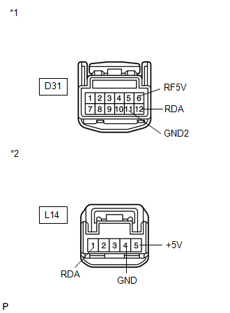
(b) Disconnect the L14 receiver connector.
(c) Measure the resistance according to the value(s) in the table below.
Standard Resistance:
|
Tester Connection |
Condition |
Specified Condition |
|---|---|---|
|
D31-12 (RDA) - L14-1 (RDA) |
Always |
Below 1 Ω |
|
D31-11 (GND2) - L14-4 (GND) |
||
|
D31-6 (RF5V) - L14-5 (+5V) |
||
|
D31-12 (RDA) - Body ground |
10 kΩ or higher |
|
|
D31-11 (GND2) - Body ground |
||
|
D31-6 (RF5V) - Body ground |
|
*1 |
Front view of wire harness connector (to Tire Pressure Warning ECU) |
|
*2 |
Front view of wire harness connector (to Tire Pressure Warning Antenna and Receiver) |
| NG | |
REPAIR OR REPLACE HARNESS OR CONNECTOR |
|
|
5. |
CHECK TRANSMITTER ID |
(a) Turn the ignition switch off.
(b) Connect the Techstream to the DLC3.
(c) Turn the ignition switch to ON.
(d) Turn the Techstream on.
(e) Enter the following menus: Chassis / Tire Pressure Monitor / Data List.
(f) Check the values by referring to the table below.
Tire Pressure Monitor|
Tester Display |
Measurement Item/Display |
Normal Condition |
Diagnostic Note |
|---|---|---|---|
|
Registered ID1 Code |
Registered ID1 code/ min.: 0 max.: FFFFFFF* |
The ID No. registered in the transmitter ID1 is displayed |
*: Displayed only when the ID No. is not registered. |
|
Registered ID2 Code |
Registered ID2 code/ min.: 0 max.: FFFFFFF* |
The ID No. registered in the transmitter ID2 is displayed |
*: Displayed only when the ID No. is not registered. |
|
Registered ID3 Code |
Registered ID3 code/ min.: 0 max.: FFFFFFF* |
The ID No. registered in the transmitter ID3 is displayed |
*: Displayed only when the ID No. is not registered. |
|
Registered ID4 Code |
Registered ID4 code/ min.: 0 max.: FFFFFFF* |
The ID No. registered in the transmitter ID4 is displayed |
*: Displayed only when the ID No. is not registered. |
(g) Check the ID number on the identified transmitter by removing it from the tire and wheel.
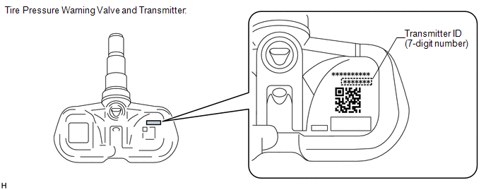
(h) Confirm that the ID number on the transmitter and recorded transmitter ID match.
|
Result |
Proceed to |
|---|---|
|
Match |
A |
|
Do not match |
B |
| B | |
GO TO STEP 7 |
|
|
6. |
REPLACE TIRE PRESSURE WARNING VALVE AND TRANSMITTER |
(a) Replace the tire pressure warning valve and transmitter (See page
).
|
|
7. |
REGISTRATION OF TRANSMITTER ID |
(a) Perform registration (See page ).
|
|
8. |
READ VALUE USING TECHSTREAM (DATA LIST) |
(a) Turn the ignition switch off.
(b) Connect the Techstream to the DLC3.
(c) Turn the ignition switch to ON.
(d) Turn the Techstream on.
(e) Enter the following menus: Chassis / Tire Pressure Monitor / Data List.
(f) Check the values by referring to the table below.
Tire Pressure Monitor|
Tester Display |
Measurement Item/Range |
Normal Condition |
Diagnostic Note |
|---|---|---|---|
|
ID1 Tire Inflation Pressure |
ID1 tire inflation pressure/ min.: Absolute pressure/ 0 kPa (0 kgf/cm2, 0 psi), Relative pressure/ -100 kPa (-1.0 kgf/cm2, -14 psi) max.: Absolute pressure/ 638 kPa (6.4 kgf/cm2, 93 psi), Relative pressure/ 538 kPa (5.4 kgf/cm2, 78 psi) |
Actual tire inflation pressure |
If 0 kPa (0 kgf/cm2, 0 psi) is displayed for absolute pressure or -100 kPa (-1.0 kgf/cm2, -14 psi) is displayed for relative pressure, data has not been received*. |
|
ID2 Tire Inflation Pressure |
ID2 tire inflation pressure/ min.: Absolute pressure/ 0 kPa (0 kgf/cm2, 0 psi), Relative pressure/ -100 kPa (-1.0 kgf/cm2, -14 psi) max.: Absolute pressure/ 638 kPa (6.4 kgf/cm2, 93 psi), Relative pressure/ 538 kPa (5.4 kgf/cm2, 78 psi) |
Actual tire inflation pressure |
If 0 kPa (0 kgf/cm2, 0 psi) is displayed for absolute pressure or -100 kPa (-1.0 kgf/cm2, -14 psi) is displayed for relative pressure, data has not been received*. |
|
ID3 Tire Inflation Pressure |
ID3 tire inflation pressure/ min.: Absolute pressure/ 0 kPa (0 kgf/cm2, 0 psi), Relative pressure/ -100 kPa (-1.0 kgf/cm2, -14 psi) max.: Absolute pressure/ 638 kPa (6.4 kgf/cm2, 93 psi), Relative pressure/ 538 kPa (5.4 kgf/cm2, 78 psi) |
Actual tire inflation pressure |
If 0 kPa (0 kgf/cm2, 0 psi) is displayed for absolute pressure or -100 kPa (-1.0 kgf/cm2, -14 psi) is displayed for relative pressure, data has not been received*. |
|
ID4 Tire Inflation Pressure |
ID4 tire inflation pressure/ min.: Absolute pressure/ 0 kPa (0 kgf/cm2, 0 psi), Relative pressure/ -100 kPa (-1.0 kgf/cm2, -14 psi) max.: Absolute pressure/ 638 kPa (6.4 kgf/cm2, 93 psi), Relative pressure/ 538 kPa (5.4 kgf/cm2, 78 psi) |
Actual tire inflation pressure |
If 0 kPa (0 kgf/cm2, 0 psi) is displayed for absolute pressure or -100 kPa (-1.0 kgf/cm2, -14 psi) is displayed for relative pressure, data has not been received*. |
HINT:
- *: It may take about 2 or 3 minutes until the values are displayed.
- If no "ID Tire Inflation Pressure" data has changed, reset the tire pressure to the appropriate specified value and rotate the tire 90 to 270 degrees. Then, rapidly release the tire pressure and recheck it.
|
Result |
Proceed to |
|---|---|
|
All tire pressure readings are equal to specified values. |
A |
|
Tire pressure values are not displayed. |
B |
| A | |
END |
|
|
9. |
REPLACE TIRE PRESSURE WARNING ANTENNA AND RECEIVER |
(a) Replace the tire pressure warning antenna and receiver (See page
).
|
|
10. |
READ VALUE USING TECHSTREAM (DATA LIST) |
(a) Turn the ignition switch off.
(b) Connect the Techstream to the DLC3.
(c) Turn the ignition switch to ON.
(d) Turn the Techstream on.
(e) Enter the following menus: Chassis / Tire Pressure Monitor / Data List.
(f) Check the values by referring to the table below.
Tire Pressure Monitor|
Tester Display |
Measurement Item/Range |
Normal Condition |
Diagnostic Note |
|---|---|---|---|
|
ID1 Tire Inflation Pressure |
ID1 tire inflation pressure/ min.: Absolute pressure/ 0 kPa (0 kgf/cm2, 0 psi), Relative pressure/ -100 kPa (-1.0 kgf/cm2, -14 psi) max.: Absolute pressure/ 638 kPa (6.4 kgf/cm2, 93 psi), Relative pressure/ 538 kPa (5.4 kgf/cm2, 78 psi) |
Actual tire inflation pressure |
If 0 kPa (0 kgf/cm2, 0 psi) is displayed for absolute pressure or -100 kPa (-1.0 kgf/cm2, -14 psi) is displayed for relative pressure, data has not been received*. |
|
ID2 Tire Inflation Pressure |
ID2 tire inflation pressure/ min.: Absolute pressure/ 0 kPa (0 kgf/cm2, 0 psi), Relative pressure/ -100 kPa (-1.0 kgf/cm2, -14 psi) max.: Absolute pressure/ 638 kPa (6.4 kgf/cm2, 93 psi), Relative pressure/ 538 kPa (5.4 kgf/cm2, 78 psi) |
Actual tire inflation pressure |
If 0 kPa (0 kgf/cm2, 0 psi) is displayed for absolute pressure or -100 kPa (-1.0 kgf/cm2, -14 psi) is displayed for relative pressure, data has not been received*. |
|
ID3 Tire Inflation Pressure |
ID3 tire inflation pressure/ min.: Absolute pressure/ 0 kPa (0 kgf/cm2, 0 psi), Relative pressure/ -100 kPa (-1.0 kgf/cm2, -14 psi) max.: Absolute pressure/ 638 kPa (6.4 kgf/cm2, 93 psi), Relative pressure/ 538 kPa (5.4 kgf/cm2, 78 psi) |
Actual tire inflation pressure |
If 0 kPa (0 kgf/cm2, 0 psi) is displayed for absolute pressure or -100 kPa (-1.0 kgf/cm2, -14 psi) is displayed for relative pressure, data has not been received*. |
|
ID4 Tire Inflation Pressure |
ID4 tire inflation pressure/ min.: Absolute pressure/ 0 kPa (0 kgf/cm2, 0 psi), Relative pressure/ -100 kPa (-1.0 kgf/cm2, -14 psi) max.: Absolute pressure/ 638 kPa (6.4 kgf/cm2, 93 psi), Relative pressure/ 538 kPa (5.4 kgf/cm2, 78 psi) |
Actual tire inflation pressure |
If 0 kPa (0 kgf/cm2, 0 psi) is displayed for absolute pressure or -100 kPa (-1.0 kgf/cm2, -14 psi) is displayed for relative pressure, data has not been received*. |
HINT:
- *: It may take about 2 or 3 minutes until the values are displayed.
- If no "ID Tire Inflation Pressure" data has changed, reset the tire pressure to the appropriate specified value and rotate the tire 90 to 270 degrees. Then, rapidly release the tire pressure and recheck it.
|
Result |
Proceed to |
|---|---|
|
All tire pressure readings are equal to specified values. |
A |
|
Tire pressure values are not displayed. |
B |
| A | |
END |
| B | |
REPLACE TIRE PRESSURE WARNING ECU |
 Engine Speed Signal Error (Test Mode DTC) (C2194/94)
DESCRIPTION
The tire pressure warning ECU receives an engine speed signal from the ECM. This
DTC is stored upon entering signal check mode (test mode), and cleared when an engine
speed signal of ...
 Abnormal Temperature Inside ID1 Tire (C2165/65-C2168/68)
DESCRIPTION
Each tire pressure warning valve and transmitter measures the tire internal temperature
as well as tire pressure, and transmits the information to the tire pressure warning
ECU along ...
Other materials about Toyota Venza:
Test Mode Procedure
TEST MODE PROCEDURE
1. WARNING LIGHT AND INDICATOR LIGHT INITIAL CHECK
(a) Release the parking brake.
NOTICE:
Before releasing the parking brake, move the shift lever to P for safety.
HINT:
When the parking brake is applied or the brake fluid level is lo ...
Removal
REMOVAL
PROCEDURE
1. RECOVER REFRIGERANT FROM REFRIGERATION SYSTEM
2. DISCONNECT CABLE FROM NEGATIVE BATTERY TERMINAL
NOTICE:
When disconnecting the cable, some systems need to be initialized after the cable
is reconnected (See page ).
3. REMOVE FR ...
Diagnosis System
DIAGNOSIS SYSTEM
1. DESCRIPTION
Active torque control 4WD system data can be read in the Data Link Connector
3 (DLC3) of the vehicle. When the system seems to be malfunctioning, use the Techstream
to check for malfunctions and perform repairs. Therefore ...

0.1615