Toyota Venza: Disassembly
DISASSEMBLY
PROCEDURE
1. REMOVE MAGNETIC CLUTCH ASSEMBLY
|
(a) Place the compressor and magnetic clutch in a vise. |
|
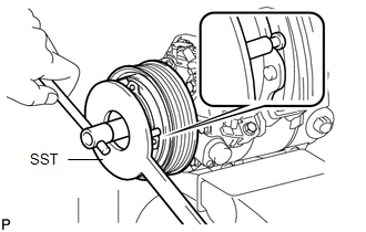
(b) Using SST, hold the magnetic clutch hub.
SST: 09985-00270
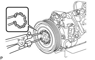
(c) Remove the bolt, magnetic clutch hub, and magnetic clutch washers.
HINT:
There is no set number of magnetic clutch washers because they are used for adjustment.
|
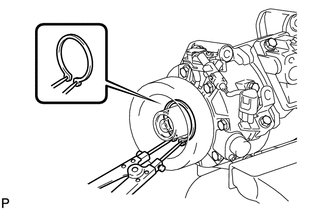
(d) Using a snap ring expander, remove the snap ring and then remove the magnetic clutch rotor. NOTICE: Take care not to damage the seal cover of the bearing when removing the snap ring. |
|
|
(e) Disconnect the connector. |
|
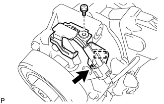
(f) Disengage the clamp.
(g) Remove the screw and the bracket.
|
(h) Using a snap ring expander, remove the snap ring and magnetic clutch stator. NOTICE: Take care not to damage the seal cover of the bearing when removing the snap ring. |
|
 Removal
REMOVAL
PROCEDURE
1. RECOVER REFRIGERANT FROM REFRIGERATION SYSTEM
2. DISCONNECT CABLE FROM NEGATIVE BATTERY TERMINAL
NOTICE:
When disconnecting the cable, some systems need to be initialized ...
 Inspection
INSPECTION
PROCEDURE
1. INSPECT COMPRESSOR AND MAGNETIC CLUTCH (A/C LOCK SENSOR)
(a) Measure the resistance according to the value(s) in the table below.
Standard Resistance:
...
Other materials about Toyota Venza:
Removal
REMOVAL
PROCEDURE
1. DISCONNECT CABLE FROM NEGATIVE BATTERY TERMINAL
NOTICE:
When disconnecting the cable, some systems need to be initialized after the cable
is reconnected (See page ).
2. REMOVE NO. 1 ENGINE COVER SUB-ASSEMBLY
3. REMOVE COOL AIR ...
Disassembly
DISASSEMBLY
PROCEDURE
1. REMOVE GENERATOR PULLEY CAP
(a) Using a screwdriver, puncture the center of the generator pulley
cap and pry it off.
NOTICE:
Do not reuse the generator pulley cap.
...
Diagnostic Trouble Code Chart
DIAGNOSTIC TROUBLE CODE CHART
ACTIVE TORQUE CONTROL 4WD SYSTEM
DTC Code
Detection Item
Trouble Area
See page
C1241/94
Low Power Supply Voltage
1. Battery
2. ECU-IG1 fuse
...

0.1589