Toyota Venza: Data Signal Circuit between Navigation Receiver Assembly and Extension Module
DESCRIPTION
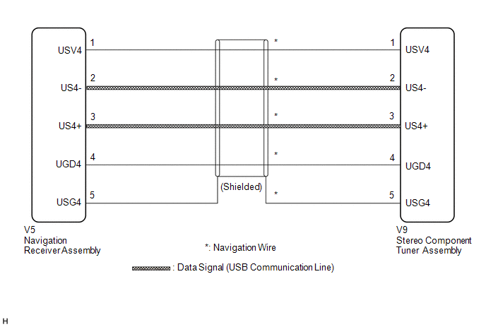
The stereo component tuner assembly sends the image data signal to the navigation receiver assembly via this circuit.
WIRING DIAGRAM
PROCEDURE
|
1. |
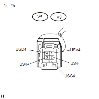
CHECK NAVIGATION WIRE |
(a) Remove the navigation wire (See page .gif) ).
).
|
(b) Measure the resistance according to the value(s) in the table below. Standard Resistance:
|
|
| OK | .gif) |
PROCEED TO NEXT SUSPECTED AREA SHOWN IN PROBLEM SYMPTOMS TABLE |
| NG | |
REPLACE NAVIGATION WIRE |
 Sound Signal Circuit between Navigation Receiver Assembly and Stereo Jack Adapter
DESCRIPTION
The No. 1 stereo jack adapter assembly sends the sound signal from an external
device to the navigation receiver assembly via this circuit.
The sound signal that has been sent is ampli ...
 Data Signal Circuit between Navigation Receiver Assembly and Stereo Jack Adapter
DESCRIPTION
The No. 1 stereo jack adapter assembly sends the sound data signal or image data
signal from a USB device to the navigation receiver assembly via this circuit.
WIRING DIAGRAM
PROCED ...
Other materials about Toyota Venza:
Installation
INSTALLATION
CAUTION / NOTICE / HINT
HINT:
Use the same procedure for the RH side and LH side.
The following procedure is for the LH side.
The rear speed sensor is a component of the rear axle hub and bearing
assembly. If the sensor malf ...
Installation
INSTALLATION
PROCEDURE
1. INSTALL REAR POWER POINT SOCKET COVER
(a) Engage the 2 claws to install the rear power point socket cover.
2. INSTALL REAR POWER POINT SOCKET ASSEMBLY
(a) Engag ...
Removal
REMOVAL
PROCEDURE
1. REMOVE FRONT SEAT HEADREST ASSEMBLY
2. REMOVE FRONT SEAT REAR OUTER TRACK COVER
3. REMOVE FRONT SEAT REAR INNER TRACK COVER
4. REMOVE FRONT SEAT ASSEMBLY
5. REMOVE SLIDE AND VERTICAL POWER SEAT SWITCH KNOB
6. REMOVE RECL ...

0.1236