Toyota Venza: Sound Signal Circuit between Navigation Receiver Assembly and Stereo Jack Adapter
DESCRIPTION
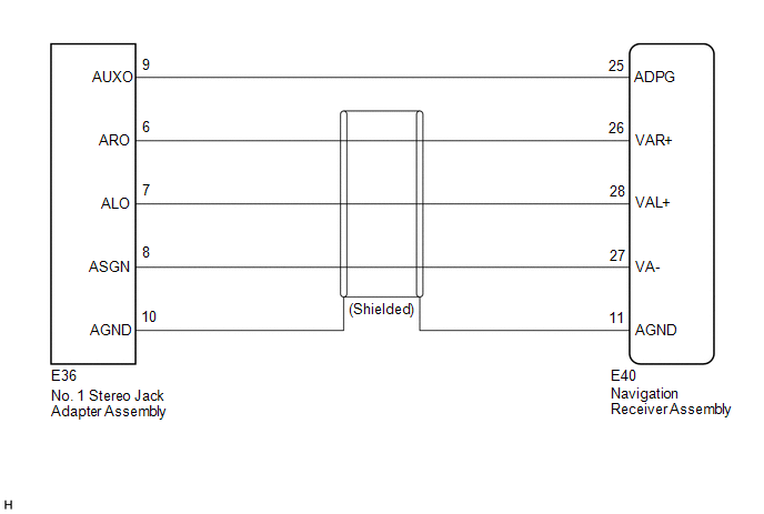
The No. 1 stereo jack adapter assembly sends the sound signal from an external device to the navigation receiver assembly via this circuit.
The sound signal that has been sent is amplified by the navigation receiver assembly and then is sent to the speakers.
If there is an open or short in the circuit, sound cannot be heard from the speakers even if there is no malfunction in the navigation receiver assembly or speakers.
WIRING DIAGRAM
PROCEDURE
|
1. |
CHECK HARNESS AND CONNECTOR (NAVIGATION RECEIVER ASSEMBLY - NO. 1 STEREO JACK ADAPTER ASSEMBLY) |
|
(a) Disconnect the E40 navigation receiver assembly connector. |
|
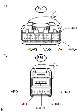
(b) Disconnect the E36 No. 1 stereo jack adapter assembly connector.
(c) Measure the resistance according to the value(s) in the table below.
Standard Resistance:
|
Tester Connection |
Condition |
Specified Condition |
|---|---|---|
|
E40-25 (ADPG) - E36-9 (AUXO) |
Always |
Below 1 Ω |
|
E40-26 (VAR+) - E36-6 (ARO) |
Always |
Below 1 Ω |
|
E40-28 (VAL+) - E36-7 (ALO) |
Always |
Below 1 Ω |
|
E40-27 (VA-) - E36-8 (ASGN) |
Always |
Below 1 Ω |
|
E40-11 (AGND) - E36-10 (AGND) |
Always |
Below 1 Ω |
|
E40-25 (ADPG) - Body ground |
Always |
10 kΩ or higher |
|
E40-26 (VAR+) - Body ground |
Always |
10 kΩ or higher |
|
E40-28 (VAL+) - Body ground |
Always |
10 kΩ or higher |
|
E40-27 (VA-) - Body ground |
Always |
10 kΩ or higher |
|
E40-11 (AGND) - Body ground |
Always |
10 kΩ or higher |
|
*a |
Front view of wire harness connector (to Navigation Receiver Assembly) |
|
*b |
Front view of wire harness connector (to No. 1 Stereo Jack Adapter Assembly) |
| OK | .gif) |
PROCEED TO NEXT SUSPECTED AREA SHOWN IN PROBLEM SYMPTOMS TABLE |
| NG | |
REPAIR OR REPLACE HARNESS OR CONNECTOR |
 Sound Signal Circuit between Navigation Receiver Assembly and Stereo Component
Amplifier
Sound Signal Circuit between Navigation Receiver Assembly and Stereo Component
Amplifier
DESCRIPTION
The navigation receiver assembly sends a sound signal to the stereo component
amplifier assembly via this circuit.
The sound signal that has been sent is amplified by the stereo compon ...
 Data Signal Circuit between Navigation Receiver Assembly and Extension Module
DESCRIPTION
The stereo component tuner assembly sends the image data signal to the navigation
receiver assembly via this circuit.
WIRING DIAGRAM
PROCEDURE
1.
CHECK NAVIG ...
Other materials about Toyota Venza:
System Description
SYSTEM DESCRIPTION
1. GENERAL
(a) To assist the driver with parking the vehicle by displaying an image of the
area behind the vehicle, this system has a rear television camera assembly mounted
on the back door. The system displays the image on the naviga ...
Tcm
Components
COMPONENTS
ILLUSTRATION
Removal
REMOVAL
CAUTION / NOTICE / HINT
NOTICE:
If automatic transmission parts are replaced, refer to Parts Replacement Compensation
Table to determine if any additional operations are necessary (See page
). ...
Removal
REMOVAL
PROCEDURE
1. REMOVE REAR DOOR SCUFF PLATE RH
HINT:
Use the same procedure for the RH side and LH side (See page
).
2. DISCONNECT REAR DOOR OPENING TRIM WEATHERSTRIP RH
HINT:
Use the same procedure for the RH side and LH side (See page
).
3. ...

0.1335