Toyota Venza: Data Signal Circuit between Navigation Receiver Assembly and Stereo Jack Adapter
DESCRIPTION
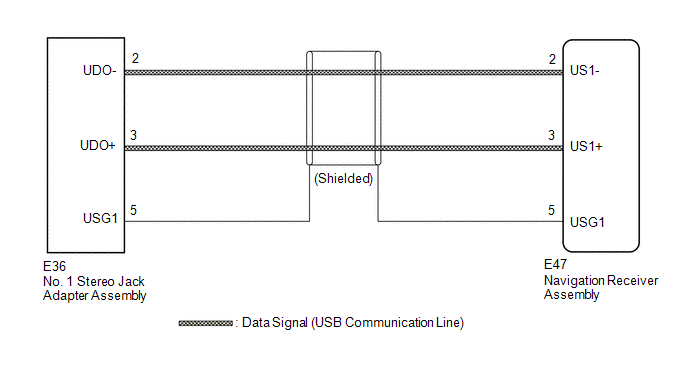
The No. 1 stereo jack adapter assembly sends the sound data signal or image data signal from a USB device to the navigation receiver assembly via this circuit.
WIRING DIAGRAM
PROCEDURE
|
1. |
CHECK HARNESS AND CONNECTOR (NAVIGATION RECEIVER ASSEMBLY - NO. 1 STEREO JACK ADAPTER ASSEMBLY) |
|
(a) Disconnect the E47 navigation receiver assembly connector. |
|
(b) Disconnect the E36 No. 1 stereo jack adapter assembly connector.
(c) Measure the resistance according to the value(s) in the table below.
Standard Resistance:
|
Tester Connection |
Condition |
Specified Condition |
|---|---|---|
|
E47-2 (US1-) - E36-2 (UDO-) |
Always |
Below 1 Ω |
|
E47-3 (US1+) - E36-3 (UDO+) |
Always |
Below 1 Ω |
|
E47-5 (USG1) - E36-5 (USG1) |
Always |
Below 1 Ω |
|
E47-2 (US1-) - Body ground |
Always |
10 kΩ or higher |
|
E47-3 (US1+) - Body ground |
Always |
10 kΩ or higher |
|
E47-5 (USG1) - Body ground |
Always |
10 kΩ or higher |
|
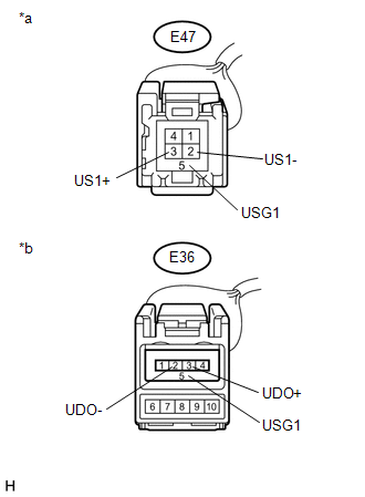
*a |
Front view of wire harness connector (to Navigation Receiver Assembly) |
|
*b |
Front view of wire harness connector (to No. 1 Stereo Jack Adapter Assembly) |
| OK | .gif) |
PROCEED TO NEXT SUSPECTED AREA SHOWN IN PROBLEM SYMPTOMS TABLE |
| NG | |
REPAIR OR REPLACE HARNESS OR CONNECTOR |
 Data Signal Circuit between Navigation Receiver Assembly and Extension Module
DESCRIPTION
The stereo component tuner assembly sends the image data signal to the navigation
receiver assembly via this circuit.
WIRING DIAGRAM
PROCEDURE
1.
CHECK NAVIG ...
 Mute Signal Circuit between Navigation Receiver Assembly and Stereo Component
Amplifier
Mute Signal Circuit between Navigation Receiver Assembly and Stereo Component
Amplifier
DESCRIPTION
This circuit sends a signal to the stereo component amplifier assembly to mute
noise. Due to this, the noise produced by changing the sound source ceases.
If there is an open in the ci ...
Other materials about Toyota Venza:
Automatic High Beam Mirror (B124A)
DESCRIPTION
The DTC is stored when the main body ECU (driver side junction block assembly)
detects malfunctions in the inner rear view mirror assembly.
DTC No.
DTC Detection Condition
Trouble Area
B124A
...
Disposal
DISPOSAL
CAUTION / NOTICE / HINT
CAUTION:
Before performing pre-disposal deployment of any SRS component, review and closely
follow all applicable environmental and hazardous material regulations. Pre-disposal
deployment may be considered hazardous mate ...
GCWR, TWR and Unbraked TWR
Confirm that the gross trailer weight, gross combination weight, gross vehicle
weight, gross axle weight and tongue weight are all within the limits.
- GCWR* and TWR*
► Vehicles without towing package
► Vehicles with towing package
...

0.1887