Toyota Venza: Installation
INSTALLATION
PROCEDURE
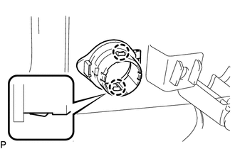
1. INSTALL REAR POWER POINT SOCKET COVER
|
(a) Engage the 2 claws to install the rear power point socket cover. |
|
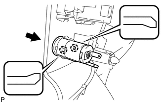
2. INSTALL REAR POWER POINT SOCKET ASSEMBLY
|
(a) Engage the 2 claws to install the rear power point socket assembly as shown in the illustration. |
|
3. INSTALL DECK TRIM SIDE PANEL ASSEMBLY RH
.gif)
4. CONNECT REAR SEAT OUTER BELT ASSEMBLY RH
HINT:
Use the same procedure for the RH side and the LH side (See page
).
5. INSTALL LUGGAGE HOLD BELT STRIKER ASSEMBLY
HINT:
Use the same procedure for the RH side and the LH side (See page
).
6. INSTALL RECLINING REMOTE CONTROL BEZEL RH
HINT:
Use the same procedure for the RH side and the LH side (See page
).
7. INSTALL REAR SEAT ASSEMBLY RH
8. CONNECT REAR SEAT RECLINING CONTROL CABLE
9. INSTALL REAR SEAT OUTER TRACK BRACKET COVER
10. INSTALL REAR SEAT INNER TRACK BRACKET COVER
11. INSTALL REAR SEAT CENTER HEADREST ASSEMBLY
12. INSTALL REAR SEAT HEADREST ASSEMBLY
13. INSTALL REAR FLOOR FINISH PLATE
14. INSTALL REAR SEAT SUB FLOOR PANEL ASSEMBLY
15. INSTALL NO. 1 DECK BOARD
16. INSTALL DECK SIDE TRIM BOX RH
17. INSTALL NO. 2 DECK BOARD SUB-ASSEMBLY
18. INSTALL DECK SIDE TRIM BOX LH
19. INSTALL NO. 3 DECK BOARD SUB-ASSEMBLY
20. INSTALL DECK BOARD ASSEMBLY
21. INSTALL TONNEAU COVER ASSEMBLY (w/ Tonneau Cover)
22. INSTALL REAR DOOR OPENING TRIM WEATHERSTRIP RH
HINT:
Use the same procedure for the RH side and the LH side (See page
).
23. INSTALL REAR DOOR SCUFF PLATE RH
HINT:
Use the same procedure for the RH side and the LH side (See page
).
 Components
COMPONENTS
ILLUSTRATION
ILLUSTRATION
ILLUSTRATION
ILLUSTRATION
...
 Removal
REMOVAL
PROCEDURE
1. REMOVE REAR DOOR SCUFF PLATE RH
HINT:
Use the same procedure for the RH side and the LH side (See page
).
2. REMOVE REAR DOOR OPENING TRIM WEATHERSTRIP RH
HINT:
Use the s ...
Other materials about Toyota Venza:
Removal
REMOVAL
PROCEDURE
1. PRECAUTION
CAUTION:
Be sure to read Precaution thoroughly before servicing (See page
).
NOTICE:
After turning the ignition switch off, waiting time may be required before disconnecting
the cable from the negative (-) battery term ...
Off-road driving
Your vehicle is not designed to be driven off-road. However, in the event that
off-road driving cannot be avoided, please observe the following precautions to
help avoid the areas prohibited to vehicles.
• Drive your vehicle only in areas where off-road ...
TC and CG Terminal Circuit
DESCRIPTION
DTC output mode is set by connecting terminals 13 (TC) and 4 (CG) of the DLC3.
The DTCs are indicated by the blinking pattern of the tire pressure warning light.
WIRING DIAGRAM
HINT:
When various warning lights blink continuously, a ground ...

0.1277