Toyota Venza: Installation
INSTALLATION
CAUTION / NOTICE / HINT
HINT:
- Use the same procedure for the RH side and LH side.
- The following procedure is for the LH side.
- The rear speed sensor is a component of the rear axle hub and bearing assembly. If the sensor malfunctions, replace the rear axle hub and bearing assembly.
- If the sensor rotor needs to be replaced, replace it together with the rear axle hub and bearing assembly.
PROCEDURE
1. INSTALL REAR AXLE HUB AND BEARING ASSEMBLY
(a) Install the rear axle hub and bearing assembly (See page
.gif) ).
).
HINT:
- The rear speed sensor is a component of the rear axle hub and bearing assembly. If the sensor malfunctions, replace the rear axle hub and bearing assembly.
- If the sensor rotor needs to be replaced, replace it together with the rear axle hub and bearing assembly.
2. INSPECT REAR AXLE HUB BEARING LOOSENESS
3. INSPECT REAR AXLE HUB RUNOUT
4. INSTALL REAR DISC
5. INSTALL REAR DISC BRAKE CALIPER ASSEMBLY
6. INSTALL REAR FLEXIBLE HOSE
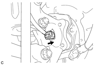
7. INSTALL REAR SPEED SENSOR WIRE
|
(a) Connect the connector to the rear speed sensor. |
|
8. INSTALL REAR WHEEL
Torque:
103 N·m {1050 kgf·cm, 76 ft·lbf}
9. CONNECT CABLE TO NEGATIVE BATTERY TERMINAL
NOTICE:
When disconnecting the cable, some systems need to be initialized after the cable
is reconnected (See page ).
10. INSPECT AND ADJUST REAR WHEEL ALIGNMENT
HINT:
(See page ).
11. CHECK FOR SPEED SENSOR SIGNAL
HINT:
(See page ).
 Removal
REMOVAL
CAUTION / NOTICE / HINT
HINT:
Use the same procedure for the RH side and LH side.
The following procedure is for the LH side.
The rear speed sensor is a component of the rea ...

Other materials about Toyota Venza:
Evaporative Emission Control System Leak Detected (Gross Leak) (P0455,P0456)
DTC SUMMARY
DTC No.
Monitoring Item
Malfunction Detection Condition
Trouble Area
Detection Timing
Detection Logic
P0455
EVAP gross leak
Leak detection pum ...
Diagnosis System
DIAGNOSIS SYSTEM
1. DESCRIPTION
(a) The certification ECU (smart key ECU assembly) and ECM control the vehicle
engine immobiliser system functions. Engine immobiliser system data and Diagnostic
Trouble Codes (DTCs) can be read through the vehicle Data Li ...
Wireless-linked Return Function does not Operate
DESCRIPTION
When a door is unlocked using the wireless unlock function or entry unlock function,
the certification ECU (smart key ECU assembly) sends a door unlock signal and key
ID signal to the main body ECU (driver side junction block assembly). When t ...

0.1257