Toyota Venza: Removal
REMOVAL
PROCEDURE
1. REMOVE FRONT SEAT HEADREST ASSEMBLY
2. REMOVE FRONT SEAT REAR OUTER TRACK COVER
.gif)
3. REMOVE FRONT SEAT REAR INNER TRACK COVER
4. REMOVE FRONT SEAT ASSEMBLY
5. REMOVE SLIDE AND VERTICAL POWER SEAT SWITCH KNOB
6. REMOVE RECLINING POWER SEAT SWITCH KNOB
7. REMOVE FRONT SEAT CUSHION SHIELD ASSEMBLY
8. REMOVE POWER SEAT SWITCH
9. REMOVE FRONT SEAT INNER BELT ASSEMBLY
10. REMOVE FRONT INNER SEAT CUSHION SHIELD
11. REMOVE SEPARATE TYPE FRONT SEAT CUSHION COVER WITH PAD
12. REMOVE FRONT SEATBACK BOARD SUB-ASSEMBLY
13. REMOVE SEPARATE TYPE FRONT SEATBACK COVER WITH PAD
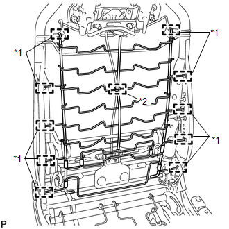
14. REMOVE LUMBAR SUPPORT ADJUSTER ASSEMBLY
|
(a) Disengage the 8 guides and clamp and remove the front seatback spring sub-assembly. Text in Illustration
|
|
(b) Disconnect the connector.
|
(c) Disengage the 2 screws and guide, and remove the lumbar support adjuster assembly. |
|
.png)
|
(d) Remove the bush. |
|
.png)
 Inspection
INSPECTION
PROCEDURE
1. INSPECT LUMBAR SUPPORT ADJUSTER ASSEMBLY
(a) Check operation of the lumbar support adjuster.
(1) Check if the lumbar support adjuster moves smoothly when the battery is c ...
 Installation
INSTALLATION
PROCEDURE
1. INSTALL LUMBAR SUPPORT ADJUSTER ASSEMBLY
(a) Install the bush.
(b) Install the lumbar support adjuste ...
Other materials about Toyota Venza:
Dtc Check / Clear
DTC CHECK / CLEAR
1. CHECK DTC
(a) Connect the Techstream to the DLC3.
(b) Turn the engine switch on (IG).
(c) Turn the Techstream on.
(d) Enter the following menus: Body Electrical / Starting Control or Power Source
Control / Trouble Codes.
(e) Read t ...
Problem Symptoms Table
PROBLEM SYMPTOMS TABLE
HINT:
Use the table below to help determine the cause of problem symptoms. If multiple
suspected areas are listed, the potential causes of the symptoms are listed in order
of probability in the "Suspected Area" column of ...
Lost Communication with AFS LIN (B124D)
DESCRIPTION
Refer to DTC B124D (Lighting system) (See page
).
DTC No.
DTC Detection Condition
Trouble Area
B124D
Malfunctions in LIN communication system
Inner rear view mir ...

0.1283