Toyota Venza: Cooling Fan Circuit
DESCRIPTION
The ECM turns on or off the fan relays using signals calculated from the engine coolant temperature, air conditioning (ON/OFF), air conditioner refrigerant pressure, engine speed, and vehicle speed signals.
The ECM switches the circuit of the cooling fan motors between series and parallel by turning on or off the fan relays in order to control the speed of the cooling fan motors in two steps.
WIRING DIAGRAM
Refer to System Diagram (See page .gif) ).
).
CAUTION / NOTICE / HINT
NOTICE:
Inspect the fuses for circuits related to this system before performing the following inspection procedure.
PROCEDURE
|
1. |
PERFORM ACTIVE TEST USING TECHSTREAM (CONTROL THE ELECTRIC COOLING FAN) |
(a) Connect the Techstream to the DLC3.
(b) Turn the ignition switch to ON.
(c) Turn the Techstream on.
(d) Enter the following menus: Powertrain / Engine / Active Test / Control the Electric Cooling Fan.
(e) Check the operation of the cooling fans while operating it using the Techstream.
OK:
|
Tester Operation |
Specified Condition |
|---|---|
|
ON |
Cooling fans operate |
|
OFF |
Cooling fans stop |
|
Result |
Proceed to |
|---|---|
|
OK |
A |
|
NG (Cooling fans do not operate) |
B |
|
NG (Cooling fans do not stop) |
C |
| A | .gif) |
PROCEED TO NEXT SUSPECTED AREA SHOWN IN PROBLEM SYMPTOMS TABLE |
| C | |
GO TO STEP 15 |
|
.gif)
|
2. |
CHECK HARNESS AND CONNECTOR (EFI MAIN RELAY - FAN NO. 1, NO. 2 OR NO. 3 RELAY) |
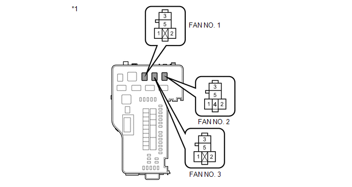
(a) Remove the FAN NO. 1, FAN NO. 2 and FAN NO. 3 relays from the engine room relay block and junction block assembly.
(b) Turn the ignition switch to ON.
(c) Measure the voltage according to the value(s) in the table below.
Standard Voltage:
|
Tester Connection |
Condition |
Specified Condition |
|---|---|---|
|
1 (FAN NO. 1 relay) - Body ground |
Ignition switch ON |
11 to 14 V |
|
1 (FAN NO. 2 relay) - Body ground |
Ignition switch ON |
11 to 14 V |
|
1 (FAN NO. 3 relay) - Body ground |
Ignition switch ON |
11 to 14 V |
|
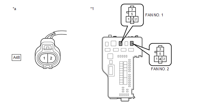
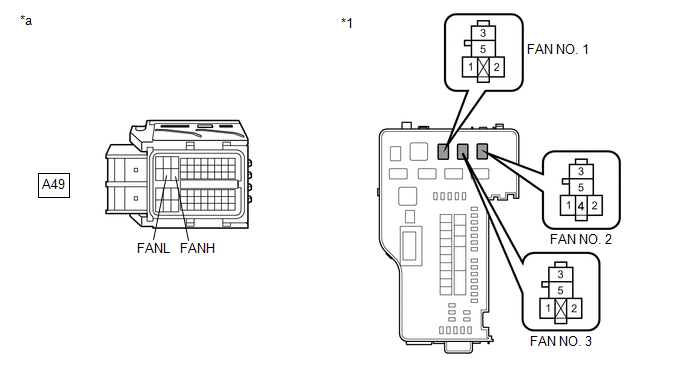
*1 |
Engine Room Relay Block and Junction Block Assembly |
(d) Reinstall the FAN NO. 1, FAN NO. 2 and FAN NO. 3 relays.
| NG | |
REPLACE ENGINE ROOM RELAY BLOCK AND JUNCTION BLOCK ASSEMBLY |
|
|
3. |
INSPECT ENGINE ROOM RELAY BLOCK AND JUNCTION BLOCK ASSEMBLY (FAN NO. 1 OR NO. 3 RELAY VOLTAGE) |
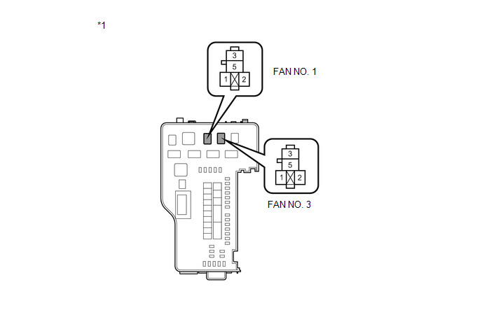
(a) Remove the FAN NO. 1 and FAN NO. 3 relays from the engine room relay block and junction block assembly.
(b) Measure the voltage according to the value(s) in the table below.
Standard Voltage:
|
Tester Connection |
Condition |
Specified Condition |
|---|---|---|
|
3 (FAN NO. 1 relay) - Body ground |
Always |
11 to 14 V |
|
5 (FAN NO. 3 relay) - Body ground |
Always |
11 to 14 V |
|
*1 |
Engine Room Relay Block and Junction Block Assembly |
(c) Reinstall the FAN NO. 1 and FAN NO. 3 relays.
| NG | |
REPAIR OR REPLACE HARNESS OR CONNECTOR (BATTERY - FAN NO. 1 OR NO. 3 RELAY) |
|
|
4. |
INSPECT FAN NO. 1 RELAY |
(a) Inspect the FAN NO. 1 relay (See page
).
| NG | |
REPLACE FAN NO. 1 RELAY |
|
|
5. |
INSPECT FAN NO. 2 RELAY |
(a) Inspect the FAN NO. 2 relay (See page
).
| NG | |
REPLACE FAN NO. 2 RELAY |
|
|
6. |
INSPECT FAN NO. 3 RELAY |
(a) Inspect the FAN NO. 3 relay (See page
).
| NG | |
REPLACE FAN NO. 3 RELAY |
|
|
7. |
CHECK HARNESS AND CONNECTOR (FAN NO. 2 RELAY - BODY GROUND) |
|
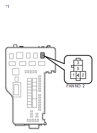
(a) Remove the FAN NO. 2 relay from the engine room relay block and junction block assembly. |
|
(b) Measure the resistance according to the value(s) in the table below.
Standard Resistance (Check for Open):
|
Tester Connection |
Condition |
Specified Condition |
|---|---|---|
|
5 (FAN NO. 2 relay) - Body ground |
Always |
Below 1 Ω |
|
*1 |
Engine Room Relay Block and Junction Block Assembly |
(c) Reinstall the FAN NO. 2 relay.
| NG | |
REPAIR OR REPLACE HARNESS OR CONNECTOR (FAN NO. 2 RELAY - BODY GROUND) |
|
|
8. |
INSPECT NO. 2 COOLING FAN MOTOR |
(a) Inspect the No. 2 cooling fan motor (See page
).
| NG | |
REPLACE NO. 2 COOLING FAN MOTOR |
|
|
9. |
CHECK HARNESS AND CONNECTOR (NO. 2 COOLING FAN MOTOR - BODY GROUND) |
|
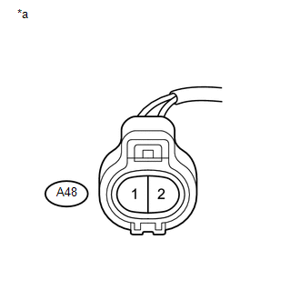
(a) Disconnect the No. 2 cooling fan motor connector. |
|
(b) Measure the resistance according to the value(s) in the table below.
Standard Resistance (Check for Open):
|
Tester Connection |
Condition |
Specified Condition |
|---|---|---|
|
A48-1 - Body ground |
Always |
Below 1 Ω |
|
*a |
Front view of wire harness connector (No. 2 cooling Fan Motor) |
(c) Reconnect the No. 2 cooling fan motor connector.
| NG | |
REPAIR OR REPLACE HARNESS OR CONNECTOR (NO. 2 COOLING FAN MOTOR - BODY GROUND) |
|
|
10. |
CHECK HARNESS AND CONNECTOR (NO. 2 COOLING FAN MOTOR - FAN NO. 1 OR NO. 2 RELAY) |
(a) Disconnect the No. 2 cooling fan motor connector.
(b) Remove the FAN NO. 1 and FAN NO. 2 relays from the engine room relay block and junction block assembly.
(c) Measure the resistance according to the value(s) in the table below.
Standard Resistance (Check for Open):
|
Tester Connection |
Condition |
Specified Condition |
|---|---|---|
|
A48-2 - 5 (FAN NO. 1 relay) |
Always |
Below 1 Ω |
|
A48-2 - 4 (FAN NO. 2 relay) |
Always |
Below 1 Ω |
Standard Resistance (Check for Short):
|
Tester Connection |
Condition |
Specified Condition |
|---|---|---|
|
A48-2 or 5 (FAN NO. 1 relay) or 4 (FAN NO. 2 relay) - Body ground |
Always |
10 kΩ or higher |
|
*1 |
Engine Room Relay Block and Junction Block Assembly |
|
*a |
Front view of wire harness connector (No. 2 cooling Fan Motor) |
(d) Reconnect the No. 2 cooling fan motor connector.
(e) Reinstall the FAN NO. 1 and FAN NO. 2 relays.
| NG | |
REPAIR OR REPLACE HARNESS OR CONNECTOR (NO. 2 COOLING FAN MOTOR - FAN NO. 1 OR NO. 2 RELAY) |
|
|
11. |
INSPECT COOLING FAN MOTOR |
(a) Inspect the cooling fan motor (See page
).
| NG | |
REPLACE COOLING FAN MOTOR |
|
|
12. |
CHECK HARNESS AND CONNECTOR (COOLING FAN MOTOR - FAN NO. 2 OR NO. 3 RELAY) |
(a) Disconnect the cooling fan motor connector.
(b) Remove the FAN NO. 2 and FAN NO. 3 relays from the engine room relay block and junction block assembly.
(c) Measure the resistance according to the value(s) in the table below.
Standard Resistance (Check for Open):
|
Tester Connection |
Condition |
Specified Condition |
|---|---|---|
|
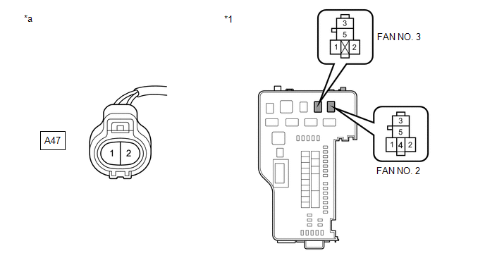
A47-1 - 3 (FAN NO. 2 relay) |
Always |
Below 1 Ω |
|
A47-2 - 3 (FAN NO. 3 relay) |
Always |
Below 1 Ω |
Standard Resistance (Check for Short):
|
Tester Connection |
Condition |
Specified Condition |
|---|---|---|
|
A47-1 or 3 (FAN NO. 2 relay) - Body ground |
Always |
10 kΩ or higher |
|
A47-2 or 3 (FAN NO. 3 relay) - Body ground |
Always |
10 kΩ or higher |
|
*1 |
Engine Room Relay Block and Junction Block Assembly |
|
*a |
Front view of wire harness connector (Cooling Fan Motor) |
(d) Reconnect the cooling fan motor connector.
(e) Reinstall the FAN NO. 2 and FAN NO. 3 relays.
| NG | |
REPAIR OR REPLACE HARNESS OR CONNECTOR (COOLING FAN MOTOR - FAN NO. 2 OR NO. 3 RELAY) |
|
|
13. |
INSPECT ENGINE ROOM RELAY BLOCK AND JUNCTION BLOCK ASSEMBLY (FAN NO. 1 RELAY - FAN NO. 2 RELAY) |
|
(a) Remove the FAN NO. 1 and FAN NO. 2 relays from the engine room relay block and junction block assembly. |
|
(b) Measure the resistance according to the value(s) in the table below.
Standard Resistance (Check for Open):
|
Tester Connection |
Condition |
Specified Condition |
|---|---|---|
|
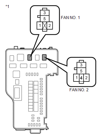
2 (FAN NO. 1 relay) - 2 (FAN NO. 2 relay) |
Always |
Below 1 Ω |
|
*1 |
Engine Room Relay Block and Junction Block Assembly |
(c) Reinstall the FAN NO. 1 and FAN NO. 2 relays.
| NG | |
REPLACE ENGINE ROOM RELAY BLOCK AND JUNCTION BLOCK ASSEMBLY |
|
|
14. |
CHECK HARNESS AND CONNECTOR (FAN NO. 2 OR NO. 3 RELAY - ECM) |
(a) Remove the FAN NO. 2 and FAN NO. 3 relays from the engine room relay block and junction block assembly.
(b) Disconnect the ECM connector.
(c) Measure the resistance according to the value(s) in the table below.
Standard Resistance (Check for Open):
|
Tester Connection |
Condition |
Specified Condition |
|---|---|---|
|
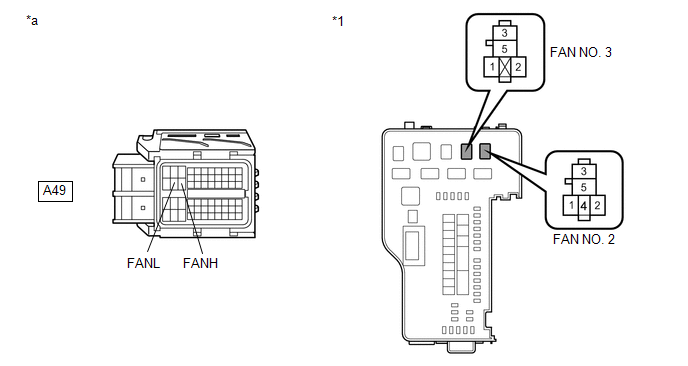
2 (FAN NO. 2 relay) - A49-22 (FANH) |
Always |
Below 1 Ω |
|
2 (FAN NO. 3 relay) - A49-21 (FANL) |
Always |
Below 1 Ω |
|
*1 |
Engine Room Relay Block and Junction Block Assembly |
|
*a |
Front view of wire harness connector (to ECM) |
(d) Reinstall the FAN NO. 2 and FAN NO. 3 relays.
(e) Reconnect the ECM connector.
| OK | |
REPLACE ECM |
| NG | |
REPAIR OR REPLACE HARNESS OR CONNECTOR (FAN NO. 2 OR NO. 3 RELAY - ECM) |
|
15. |
INSPECT FAN NO. 1 RELAY |
(a) Inspect the FAN NO. 1 relay (See page
).
| NG | |
REPLACE FAN NO. 1 RELAY |
|
|
16. |
INSPECT FAN NO. 3 RELAY |
(a) Inspect the FAN NO. 3 relay (See page
).
| NG | |
REPLACE FAN NO. 3 RELAY |
|
|
17. |
CHECK HARNESS AND CONNECTOR (FAN NO. 1, NO. 2 OR NO. 3 RELAY - ECM) |
(a) Remove the FAN NO. 1, FAN NO. 2 and FAN NO. 3 relays from the engine room relay block and junction block assembly.
(b) Disconnect the ECM connector.
(c) Measure the resistance according to the value(s) in the table below.
Standard Resistance (Check for Short):
|
Tester Connection |
Condition |
Specified Condition |
|---|---|---|
|
2 (FAN NO. 1 relay) or 2 (FAN NO. 2 relay) or A49-22 (FANH) - Body ground |
Always |
10 kΩ or higher |
|
2 (FAN NO. 3 relay) or A49-21 (FANL) - Body ground |
Always |
10 kΩ or higher |
|
*1 |
Engine Room Relay Block and Junction Block Assembly |
|
*a |
Front view of wire harness connector (to ECM) |
(d) Reinstall the FAN NO. 1, FAN NO. 2 and FAN NO. 3 relays.
(e) Reconnect the ECM connector.
| OK | |
REPLACE ECM |
| NG | |
REPAIR OR REPLACE HARNESS OR CONNECTOR (FAN NO. 1, NO. 2 OR NO. 3 RELAY - ECM) |
 Problem Symptoms Table
PROBLEM SYMPTOMS TABLE
Use the table below to help determine the cause of problem symptoms. If multiple
suspected areas are listed, the potential causes of the symptoms are listed in order
of pro ...
 On-vehicle Inspection
ON-VEHICLE INSPECTION
PROCEDURE
1. INSPECT COOLING FAN OPERATION AT LOW TEMPERATURES (Below 83°C (181°F))
(a) Turn the ignition switch to ON.
(b) Check that the cooling fans stop.
If not, check ...
Other materials about Toyota Venza:
Multi-information display (LCD type)
The multi-information display presents the driver with a variety of driving-related
data, including the clock and current outside temperature.
• Clock
Indicates and sets the time.
• Outside temperature
Indicates the outside temperature.
The temper ...
Removal
REMOVAL
CAUTION / NOTICE / HINT
HINT:
Perform "Inspection After Repair" after replacing the fuel pump assembly (See
page ).
PROCEDURE
1. DISCHARGE FUEL SYSTEM PRESSURE
(a) Discharge fuel system pressure (See page
).
2. DISCONNECT CABLE FR ...
System Description
SYSTEM DESCRIPTION
1. LIN COMMUNICATION SYSTEM DESCRIPTION
The LIN communication system is used for communication between the components
in the table below. If communication cannot be performed through LIN communication
because of an open in the communic ...

0.1637