Toyota Venza: Removal
REMOVAL
PROCEDURE
1. REMOVE REAR DOOR SCUFF PLATE
.gif)
2. DISCONNECT REAR DOOR OPENING TRIM WEATHERSTRIP
3. REMOVE TONNEAU COVER ASSEMBLY (w/ Tonneau Cover)
4. REMOVE DECK BOARD ASSEMBLY
5. REMOVE NO. 3 DECK BOARD SUB-ASSEMBLY
6. REMOVE DECK SIDE TRIM BOX LH
7. REMOVE NO. 2 DECK BOARD SUB-ASSEMBLY
8. REMOVE DECK SIDE TRIM BOX RH
9. REMOVE NO. 1 DECK BOARD
10. REMOVE REAR SEAT SUB FLOOR PANEL ASSEMBLY
11. REMOVE REAR FLOOR FINISH PLATE
12. REMOVE REAR SEAT HEADREST ASSEMBLY (for LH Side)
13. REMOVE REAR SEAT INNER TRACK BRACKET COVER (for LH Side)
14. REMOVE REAR SEAT OUTER TRACK BRACKET COVER (for LH Side)
15. DISCONNECT REAR SEAT NO. 2 RECLINING CONTROL CABLE SUB-ASSEMBLY (for LH Side)
16. REMOVE REAR SEAT ASSEMBLY LH (for LH Side)
17. REMOVE REAR SEAT HEADREST ASSEMBLY (for RH Side)
18. REMOVE REAR SEAT CENTER HEADREST ASSEMBLY (for RH Side)
19. REMOVE REAR SEAT INNER TRACK BRACKET COVER (for RH Side)
20. REMOVE REAR SEAT OUTER TRACK BRACKET COVER (for RH Side)
21. DISCONNECT REAR SEAT RECLINING CONTROL CABLE SUB-ASSEMBLY (for RH Side)
22. REMOVE REAR SEAT ASSEMBLY RH (for RH Side)
23. REMOVE RECLINING REMOTE CONTROL BEZEL
24. REMOVE LUGGAGE HOLD BELT STRIKER ASSEMBLY
25. DISCONNECT REAR SEAT OUTER BELT ASSEMBLY
26. REMOVE DECK TRIM SIDE PANEL ASSEMBLY LH (for LH Side)
27. REMOVE DECK TRIM SIDE PANEL ASSEMBLY RH (for RH Side)
28. REMOVE REAR BUMPER PLATE LH
29. REMOVE REAR BUMPER PLATE RH
30. REMOVE REAR BUMPER ASSEMBLY
31. REMOVE REAR COMBINATION LIGHT ASSEMBLY
|
(a) Remove the 2 nuts. |
|
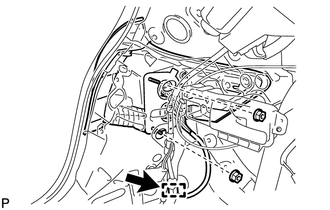
(b) Disconnect the connector.
(c) Disengage the clamp.
|
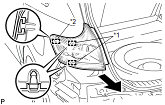
(d) Disengage the 2 pins and guide, and remove the rear combination light assembly as shown in the illustration. Text in Illustration
|
|
 On-vehicle Inspection
ON-VEHICLE INSPECTION
PROCEDURE
1. INSPECT REAR COMBINATION LIGHT ASSEMBLY
(a) Disconnect the connector from the rear combination light assembly.
...
 Disassembly
DISASSEMBLY
PROCEDURE
1. REMOVE TAIL AND STOP LIGHT BULB
(a) Turn the tail and stop light bulb and the rear combination light
socket and wire in the direction indicated by the arrow ...
Other materials about Toyota Venza:
Installation
INSTALLATION
PROCEDURE
1. INSTALL SPIRAL WITH SENSOR CABLE SUB-ASSEMBLY
(a) Install the spiral with sensor cable sub-assembly (See page
).
NOTICE:
Do not replace the spiral cable with the battery connected and the engine
switch on (IG).
...
Automatic air conditioning system
Airflow and outlets are automatically adjusted according to the temperature
setting.
► Control panel
► Multi-information display (TFT type)
The settings display will differ according to the situation. If
is pressed while in automat ...
Installation
INSTALLATION
PROCEDURE
1. TEMPORARILY TIGHTEN PROPELLER WITH CENTER BEARING SHAFT ASSEMBLY
(a) Remove SST from the transfer.
SST: 09325-20010
(b) Install the propeller with center bearing shaft ...

0.1255