Toyota Venza: Console Box Light
Components
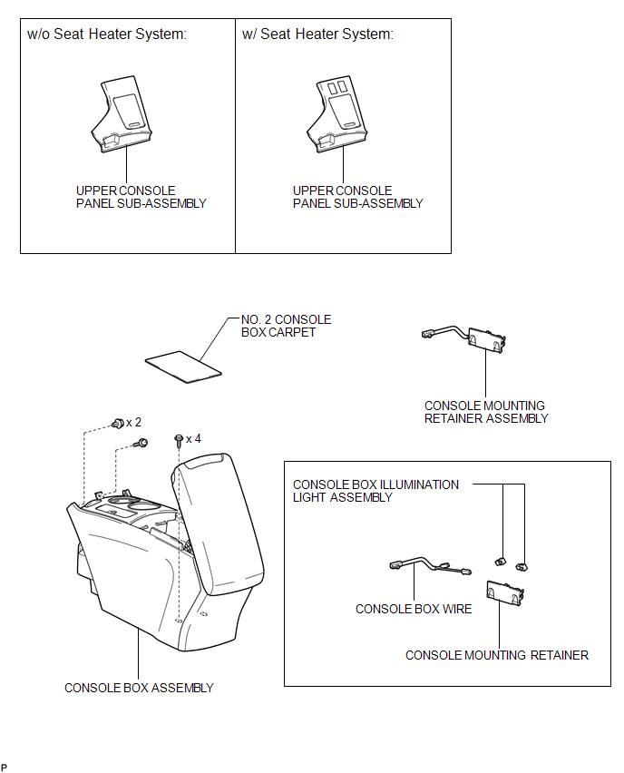
COMPONENTS
ILLUSTRATION
Removal
REMOVAL
PROCEDURE
1. REMOVE UPPER CONSOLE PANEL SUB-ASSEMBLY (w/o Seat Heater System)
.gif)
2. REMOVE UPPER CONSOLE PANEL SUB-ASSEMBLY (w/ Seat Heater System)
3. REMOVE NO. 2 CONSOLE BOX CARPET
4. REMOVE CONSOLE BOX ASSEMBLY
5. REMOVE CONSOLE MOUNTING RETAINER ASSEMBLY
6. REMOVE CONSOLE BOX WIRE
7. REMOVE CONSOLE BOX ILLUMINATION LIGHT ASSEMBLY
|
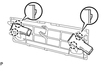
(a) Disengage the 4 claws and remove the 2 console box illumination light assemblies. |
|
Inspection
INSPECTION
PROCEDURE
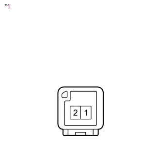
1. INSPECT CONSOLE BOX ILLUMINATION LIGHT ASSEMBLY
|
(a) Connect a positive (+) lead from the battery to terminal 2 and a negative (-) lead to terminal 1. |
|
(b) Check that the console box illumination light comes on.
OK:
Console box illumination light comes on.
Text in Illustration|
*1 |
Component without harness connected (Console Box Illumination Light Assembly) |
If the result is not as specified, replace the console box illumination light assembly.
Installation
INSTALLATION
PROCEDURE
1. INSTALL CONSOLE BOX ILLUMINATION LIGHT ASSEMBLY
|
(a) Engage the 4 claws to install the 2 console box illumination light assemblies. |
|
.png)
2. INSTALL CONSOLE BOX WIRE
.gif)
3. INSTALL CONSOLE MOUNTING RETAINER ASSEMBLY
4. INSTALL CONSOLE BOX ASSEMBLY
5. INSTALL NO. 2 CONSOLE BOX CARPET
6. INSTALL UPPER CONSOLE PANEL SUB-ASSEMBLY (w/o Seat Heater System)
7. INSTALL UPPER CONSOLE PANEL SUB-ASSEMBLY (w/ Seat Heater System)
 Back Door Courtesy Switch
Components
COMPONENTS
ILLUSTRATION
Removal
REMOVAL
PROCEDURE
1. REMOVE BACK DOOR PANEL TRIM ASSEMBLY
2. REMOVE BACK DOOR LOCK ASSEMBLY
(a) Disconnect the connector.
...
 Door Courtesy Light
Components
COMPONENTS
ILLUSTRATION
Removal
REMOVAL
PROCEDURE
1. REMOVE COURTESY LIGHT ASSEMBLY
(a) Using a screwdriver wrapped with protective tape, disengage the claw.
Text ...
Other materials about Toyota Venza:
Disassembly
DISASSEMBLY
PROCEDURE
1. REMOVE POSITION INDICATOR HOUSING SUB-ASSEMBLY
(a) Remove the shift lever cap from the position indicator housing sub-assembly.
(b) Disengage the 4 claws and remove the position indicator housing sub-assembly.
...
System Diagram
SYSTEM DIAGRAM
Communication Table
Sender
Receiver
Signal
Line
Main Body ECU
(Driver Side Junction Block Assembly)
Clearance Warning ECU Assembly
Destination information
...
Black Screen
PROCEDURE
1.
CHECK DISPLAY SETTING
(a) Check that the display is not in screen off mode.
OK:
The display setting is not in screen off mode.
NG
CHANGE SCREEN TO SCREEN ON MODE
...

0.1546