Toyota Venza: Installation
INSTALLATION
PROCEDURE
1. INSTALL ATF TEMPERATURE SENSOR ASSEMBLY
|
(a) Coat a new O-ring with ATF and install it to the ATF temperature sensor assembly. Text in Illustration
|
|
.png)
(b) Coat the 4 bolts with ATF.
|
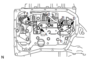
(c) Install the ATF temperature sensor assembly and clamp to the transmission valve body assembly with the 4 bolts. Text in Illustration
Torque: 11 N·m {112 kgf·cm, 8 ft·lbf} Bolt length: Bolt (A) 25 mm (0.984 in.) Bolt (B) 85 mm (3.35 in.) |
|
(d) Connect the ATF temperature sensor assembly connector.
2. INSTALL VALVE BODY OIL STRAINER ASSEMBLY
.gif)
3. INSTALL AUTOMATIC TRANSAXLE OIL PAN SUB-ASSEMBLY
4. INSTALL AUTOMATIC TRANSAXLE ASSEMBLY
HINT:
See the steps from "Install Automatic Transaxle Assembly" through "Install Engine
Assembly with Transaxle" (See page ).
 Inspection
INSPECTION
PROCEDURE
1. INSPECT ATF TEMPERATURE SENSOR ASSEMBLY
(a) Measure the resistance according to the value(s) in the table below.
Standard Resistance:
Test ...
 Atf Temperature Sensor(when Using The Engine Support Bridge)
Components
COMPONENTS
ILLUSTRATION
Inspection
INSPECTION
PROCEDURE
1. INSPECT ATF TEMPERATURE SENSOR ASSEMBLY
(a) Measure the resistance according to the value(s) in the table ...
Other materials about Toyota Venza:
Removal
REMOVAL
CAUTION / NOTICE / HINT
HINT:
Use the same procedure for the RH side and LH side.
The procedure listed below is for the LH side.
PROCEDURE
1. REMOVE REAR WHEEL
2. SEPARATE NO. 3 PARKING BRAKE CABLE ASSEMBLY
(a) Remov ...
Removal
REMOVAL
CAUTION / NOTICE / HINT
NOTICE:
Make sure to select FACE mode before disconnecting the cable from the negative
(-) battery terminal.
PROCEDURE
1. RECOVER REFRIGERANT FROM REFRIGERATION SYSTEM
2. REMOVE WINDSHIELD WIPER MOTOR AND LINK ASSEMBL ...
Blower Motor Circuit
DESCRIPTION
The blower motor is operated by signals from the A/C amplifier. Blower motor
speed signals are transmitted in accordance with changes in the duty ratio.
WIRING DIAGRAM
CAUTION / NOTICE / HINT
NOTICE:
Inspect the fuses for circuits related ...

0.1194