Toyota Venza: Back Door Courtesy Switch
Components
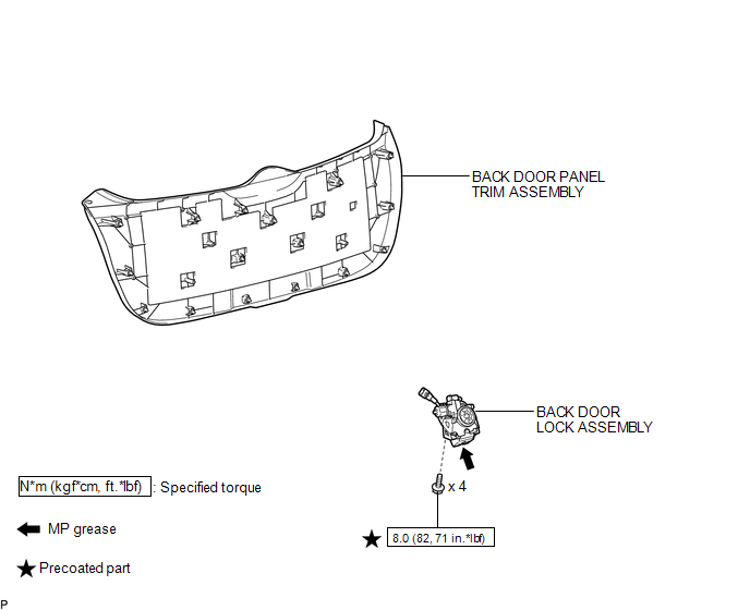
COMPONENTS
ILLUSTRATION
Removal
REMOVAL
PROCEDURE
1. REMOVE BACK DOOR PANEL TRIM ASSEMBLY
.gif)
2. REMOVE BACK DOOR LOCK ASSEMBLY
|
(a) Disconnect the connector. |
|
.png)
(b) Disengage the clamp.
(c) Remove the bolt.
|
(d) Remove the 3 bolts and back door lock assembly. |
|
.png)
Inspection
INSPECTION
PROCEDURE
1. INSPECT BACK DOOR COURTESY SWITCH (BACK DOOR LOCK ASSEMBLY)
(a) Measure the resistance according to the value(s) in the table below.
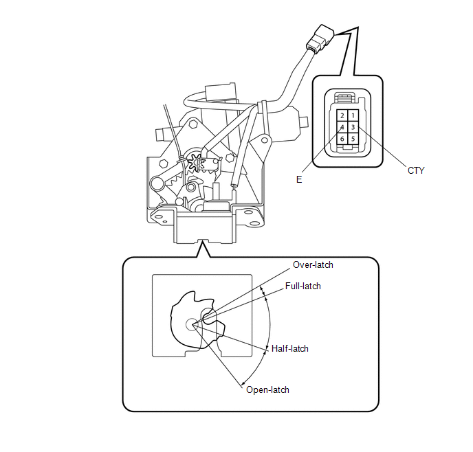
Standard Resistance:
|
Tester Connection |
Condition |
Specified Condition |
|---|---|---|
|
3 (CTY) - 4 (E) |
Open-latched |
Below 1 Ω |
|
3 (CTY) - 4 (E) |
Half-latched |
Below 1 Ω |
|
3 (CTY) - 4 (E) |
Full-latched |
10 kΩ or higher |
|
3 (CTY) - 4 (E) |
Over-latched |
10 kΩ or higher |
If the result is not specified, replace the back door lock assembly.
Installation
INSTALLATION
PROCEDURE
1. INSTALL BACK DOOR LOCK ASSEMBLY
(a) Apply MP grease to the sliding parts of the back door lock assembly.
(b) Apply adhesive to the threads of the bolt.
Adhesive:
Toyota Genuine Adhesive 1324, Three Bond 1324 or equivalent
|
(c) Install the back door lock assembly with the 3 bolts. Torque: 8.0 N·m {82 kgf·cm, 71 in·lbf} |
|
.png)
|
(d) Install the bolt. Torque: 8.0 N·m {82 kgf·cm, 71 in·lbf} |
|
.png)
(e) Engage the clamp.
(f) Connect the connector.
2. INSTALL BACK DOOR PANEL TRIM ASSEMBLY
.gif)
 Lighting (int)
...
 Console Box Light
Components
COMPONENTS
ILLUSTRATION
Removal
REMOVAL
PROCEDURE
1. REMOVE UPPER CONSOLE PANEL SUB-ASSEMBLY (w/o Seat Heater System)
2. REMOVE UPPER CONSOLE PANEL SUB-ASSEMBLY (w/ Seat Hea ...
Other materials about Toyota Venza:
Dtc Check / Clear
DTC CHECK / CLEAR
1. CHECK DTC
(a) Connect the Techstream to the DLC3.
(b) Turn the ignition switch to ON.
(c) Turn the Techstream on.
(d) Enter the following menus: Body Electrical / Navigation System / Trouble
Codes.
(e) Check for DTCs (See page ).
...
How To Proceed With Troubleshooting
CAUTION / NOTICE / HINT
PRECAUTIONS WHEN TROUBLESHOOTING
NOTICE:
DTCs for the CAN communication system are as follows: U0073, U0100,
U0101, U0123, U0124, U0126, U0129, U0131, U0142, U0155, U0164, U0182, U0199,
U0200, U0208, U0230, U1002 and ...
Certification ECU Communication Stop Mode
DESCRIPTION
Detection Item
Symptom
Trouble Area
Certification ECU Communication Stop Mode
"Smart Access/Smart Key/Wireless Tuner" is not displayed on
"CAN Bus Check&q ...

0.1614