Toyota Venza: Radio Broadcast cannot be Received or Poor Reception
PROCEDURE
|
1. |
CHECK RADIO AND DISPLAY RECEIVER ASSEMBLY |
(a) Check the radio automatic station search function.
(1) Check the radio automatic station search function by activating it.
|
Result |
Proceed to |
|---|---|
|
Automatic station search function does not stop. |
A |
|
Automatic station search function stops on a station. |
B |
| B | .gif) |
REPLACE RADIO AND DISPLAY RECEIVER ASSEMBLY |
|
.gif)
|
2. |
CHECK OPTIONAL COMPONENTS |
(a) Check if any optional components that may decrease reception capacity, such as sunshade film or a telephone antenna, are installed.
|
Result |
Proceed to |
|---|---|
|
Optional components are not installed. |
A |
|
Optional components are installed. |
B |
NOTICE:
Do not remove optional components without the permission of the customer.
| B | |
REMOVE OPTIONAL COMPONENTS AND CHECK AGAIN (SEE NOTICE ABOVE) |
|
|
3. |
CHECK RADIO ANTENNA |
(a) Preparation for check
(1) Remove the roof antenna pole sub-assembly from the satellite radio antenna assembly (w/ SDARS System).
(2) Remove the roof antenna pole sub-assembly from the amplifier antenna assembly (for Roof) (w/o SDARS System).
(b) Check for noise
(1) Turn the ignition switch to ACC with the radio and display receiver assembly connector connected.
(2) Turn the radio and display receiver assembly on and enter AM mode.
(3) Place a screwdriver, thin wire or other metal object on the threaded portion of the satellite radio antenna assembly for installation of the roof antenna pole sub-assembly and check that noise can be heard from the speakers (w/ SDARS System).
(4) Place a screwdriver, thin wire or other metal object on the threaded portion of the amplifier antenna assembly (for Roof) for installation of the roof antenna pole sub-assembly and check that noise can be heard from the speakers (w/o SDARS System).
OK:
Noise can be heard from the speakers.
| NG | |
REPLACE RADIO AND DISPLAY RECEIVER ASSEMBLY |
|
|
4. |
CHECK RADIO AND DISPLAY RECEIVER ASSEMBLY |
|
(a) Preparation for check (1) Disconnect the antenna connector from the radio and display receiver assembly. |
|
(b) Check for noise
(1) Turn the ignition switch to ACC with the radio and display receiver assembly connector connected.
(2) Turn the radio on and tune into AM mode.
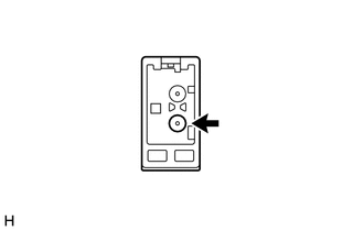
(3) Place a screwdriver, thin wire or other metal object on the radio and display receiver assembly antenna jack and check that noise can be heard from the speakers.
OK:
Noise can be heard from the speakers.
| NG | |
REPLACE RADIO AND DISPLAY RECEIVER ASSEMBLY |
|
|
5. |
INSPECT RADIO AND DISPLAY RECEIVER ASSEMBLY |
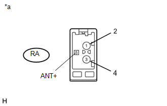
(a) Disconnect the RA radio and display receiver assembly connector.
|
(b) Measure the voltage according to the value(s) in the table below. Standard Voltage:
|
|
| NG | |
REPLACE RADIO AND DISPLAY RECEIVER ASSEMBLY |
|
|
6. |
REPLACE ANTENNA CORD SUB-ASSEMBLY |
(a) Replace the antenna cord sub-assembly with a new or known good one and check
if radio broadcasts can be received normally (See page
.gif) ).
).
OK:
Radio broadcasts can be received normally.
| OK | |
END |
|
|
7. |
REPLACE NO. 2 ANTENNA CORD SUB-ASSEMBLY |
(a) Replace the No. 2 antenna cord sub-assembly with a new or known good one
and check if radio broadcasts can be received normally (See page
).
OK:
Radio broadcasts can be received normally.
| OK | |
END |
|
|
8. |
REPLACE NO. 3 ANTENNA CORD SUB-ASSEMBLY |
(a) Replace the No. 3 antenna cord sub-assembly with a new or known good one
and check if radio broadcasts can be received normally (See page
).
OK:
Radio broadcasts can be received normally.
| OK | |
END |
|
|
9. |
CHECK ROOF ANTENNA POLE SUB-ASSEMBLY |
(a) Check that the roof antenna pole sub-assembly is securely installed (See
page ).
OK:
The roof antenna pole sub-assembly is installed properly.
(b) Proceed to the next step based on the inspection result.
|
Condition |
Proceed to |
|---|---|
|
NG |
A |
|
OK (w/ SDARS System) |
B |
|
OK (w/o SDARS System) |
C |
| A | |
CHECK AND REPLACE ROOF ANTENNA POLE SUB-ASSEMBLY |
| C | |
GO TO STEP 11 |
|
|
10. |
REPLACE SATELLITE RADIO ANTENNA ASSEMBLY |
(a) Replace the satellite radio antenna assembly with a new or known good one
and check if radio broadcasts can be received normally (See page
).
OK:
Radio broadcasts can be received normally.
| OK | |
END |
| NG | |
REPLACE RADIO AND DISPLAY RECEIVER ASSEMBLY |
|
11. |
REPLACE AMPLIFIER ANTENNA ASSEMBLY (for Roof) |
(a) Replace the amplifier antenna assembly (for Roof) with a new or known good
one and check if radio broadcasts can be received normally (See page
).
OK:
Radio broadcasts can be received normally.
| OK | |
END |
| NG | |
REPLACE RADIO AND DISPLAY RECEIVER ASSEMBLY |
 CD Sound Skips
PROCEDURE
1.
CHECK CD
(a) Check that the CD is not deformed or cracked.
OK:
No deformation or cracks on the CD
...
 Illumination for Panel Switch does not Come on with Tail Switch ON
PROCEDURE
1.
CHECK VEHICLE SIGNAL (OPERATION CHECK)
(a) Enter the "Vehicle Signal Check Mode" screen. Refer to Check Vehicle Signal
in Operation Check (Se ...
Other materials about Toyota Venza:
Diagnostic Trouble Code Chart
DIAGNOSTIC TROUBLE CODE CHART
Audio and Visual System
DTC Code
Detection Item
See page
B1532
LVDS Signal Malfunction (from Extension Module)
B1551
HD Radio ...
Catalyst System Efficiency Below Threshold (Bank 1) (P0420)
MONITOR DESCRIPTION
The ECM uses sensors mounted in front of and behind the Three-Way Catalytic Converter
(TWC) to monitor its efficiency.
The first sensor, the air fuel ratio sensor, sends pre-catalyst information to
the ECM. The second sensor, the heat ...
Front Passenger Side Power Window does not Operate with Front Passenger Side
Power Window Switch
DESCRIPTION
When the engine is running or the ignition switch is ON, the power window regulator
motor assembly (for front passenger side) is operated by the power window regulator
switch assembly (for front passenger side). The power window regulator moto ...

0.1269