Toyota Venza: Door Courtesy Light
Components
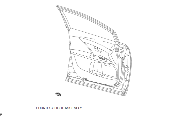
COMPONENTS
ILLUSTRATION
Removal
REMOVAL
PROCEDURE
1. REMOVE COURTESY LIGHT ASSEMBLY
|
(a) Using a screwdriver wrapped with protective tape, disengage the claw. Text in Illustration
|
|
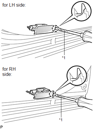
(b) Disconnect the connector and remove the courtesy light assembly.
Inspection
INSPECTION
PROCEDURE
1. INSPECT COURTESY LIGHT ASSEMBLY
|
(a) Connect a positive (+) lead from the battery to terminal 2 and a negative (-) lead to terminal 1. |
|
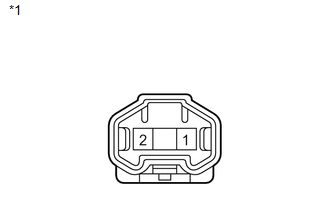
(b) Check that the courtesy light comes on.
OK:
Courtesy light comes on.
Text in Illustration|
*1 |
Component without harness connected (Courtesy Light Assembly) |
If the result is not as specified, replace the bulb or courtesy light assembly.
Installation
INSTALLATION
PROCEDURE
1. INSTALL COURTESY LIGHT ASSEMBLY
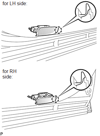
(a) Connect the connector.
|
(b) Engage the claw to install the courtesy light assembly. |
|
 Console Box Light
Components
COMPONENTS
ILLUSTRATION
Removal
REMOVAL
PROCEDURE
1. REMOVE UPPER CONSOLE PANEL SUB-ASSEMBLY (w/o Seat Heater System)
2. REMOVE UPPER CONSOLE PANEL SUB-ASSEMBLY (w/ Seat Hea ...
 Front Door Courtesy Switch
Components
COMPONENTS
ILLUSTRATION
Inspection
INSPECTION
PROCEDURE
1. INSPECT COURTESY LIGHT SWITCH
(a) Measure the resistance according to the value(s) in the table below.
Standard Re ...
Other materials about Toyota Venza:
Operation Check
OPERATION CHECK
1. CHECK POWER DOOR LOCK CONTROL OPERATION
NOTICE:
The following procedure is based on the assumption that the functions have not
been customized using the Techstream.
(a) Check basic functions.
(1) Check that all doors lock when the loc ...
Operation Check
OPERATION CHECK
1. CHECK WINDOW LOCK SWITCH
HINT:
Before performing the window lock switch operation check, make sure that the
window lock switch is off (the switch is not pushed in).
(a) Check that the front passenger and rear windows cannot be operat ...
Entire Combination Meter does not Operate
DESCRIPTION
This circuit is the power source circuit for the meter. This circuit provides
two types of power sources; one is a constant power source mainly used as a backup
power source, and the other is an IG power source mainly used for signal transmiss ...

0.115