Toyota Venza: Compressor Solenoid Circuit (B1451/51)
DESCRIPTION
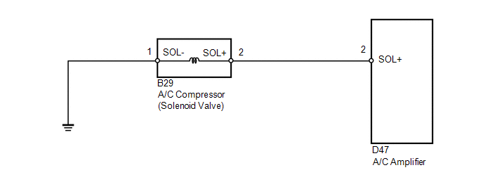
In this circuit, the A/C compressor receives a refrigerant compression demand signal from the A/C amplifier.
Based on this signal, the A/C compressor changes the amount of compressor output.
|
DTC No. |
DTC Detection Condition |
Trouble Area |
|---|---|---|
|
B1451/51 |
Open or short in A/C compressor solenoid circuit |
|
WIRING DIAGRAM
PROCEDURE
|
1. |
INSPECT A/C COMPRESSOR (SOLENOID VALVE) |
|
(a) Disconnect the A/C compressor (solenoid valve) connector. |
|
(b) Measure the resistance according to the value(s) in the table below.
Standard Resistance:
|
Tester Connection |
Condition |
Specified Condition |
|---|---|---|
|
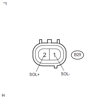
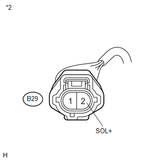
B29-2 (SOL+) - B29-1 (SOL-) |
20°C (68°F) |
10 to 11 Ω |
|
Result |
Proceed to |
|---|---|
|
OK |
A |
|
NG (for 2GR-FE) |
B |
|
NG (for 1AR-FE) |
C |
|
*1 |
Component without harness connected (A/C Compressor (Solenoid Valve)) |
| B | .gif) |
REPLACE A/C COMPRESSOR (SOLENOID VALVE) |
| C | |
REPLACE A/C COMPRESSOR (SOLENOID VALVE) |
|
.gif)
|
2. |
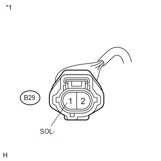
CHECK HARNESS AND CONNECTOR (A/C COMPRESSOR (SOLENOID VALVE) - BODY GROUND) |
|
(a) Measure the resistance according to the value(s) in the table below. Standard Resistance:
|
|
| NG | |
REPAIR OR REPLACE HARNESS OR CONNECTOR |
|
|
3. |
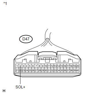
CHECK HARNESS AND CONNECTOR (A/C COMPRESSOR (SOLENOID VALVE) - A/C AMPLIFIER) |
|
(a) Disconnect the A/C amplifier connector. |
|
|
(b) Measure the resistance according to the value(s) in the table below. Standard Resistance:
Result:
|
|
| A | |
REPAIR OR REPLACE HARNESS OR CONNECTOR |
| B | |
PROCEED TO NEXT SUSPECTED AREA SHOWN IN PROBLEM SYMPTOMS TABLE |
| C | |
REPLACE A/C AMPLIFIER |
 Driver Side Solar Sensor Short Circuit (B14A2)
DESCRIPTION
The solar sensor is installed on the upper side of the instrument panel. It detects
sunlight to control air conditioning AUTO mode. The output voltage from the solar
sensor varies i ...
 BUS IC Communication Malfunction (B1497/97)
DESCRIPTION
The air conditioning harness connects the A/C amplifier and each servo. The A/C
amplifier supplies power and sends operation instructions to each servo through
the air conditioning ha ...
Other materials about Toyota Venza:
How To Proceed With Troubleshooting
CAUTION / NOTICE / HINT
HINT:
Use the following procedures to troubleshoot the power back door system.
*: Use the Techstream.
PROCEDURE
1.
VEHICLE BROUGHT TO WORKSHOP
NEXT
...
Removal
REMOVAL
PROCEDURE
1. REMOVE REAR DOOR SCUFF PLATE RH
HINT:
Use the same procedure for the RH side and the LH side (See page
).
2. REMOVE REAR DOOR OPENING TRIM WEATHERSTRIP RH
HINT:
Use the same procedure for the RH side and the LH side (See page
). ...
Removal
REMOVAL
CAUTION / NOTICE / HINT
HINT:
Use the same procedure for the RH side and LH side.
The procedure listed below is for the LH side.
PROCEDURE
1. REMOVE REAR WHEEL
2. SEPARATE REAR SPEED SENSOR
3. REMOVE REAR AXLE SHAFT NUT
...

0.1167