Toyota Venza: System Diagram
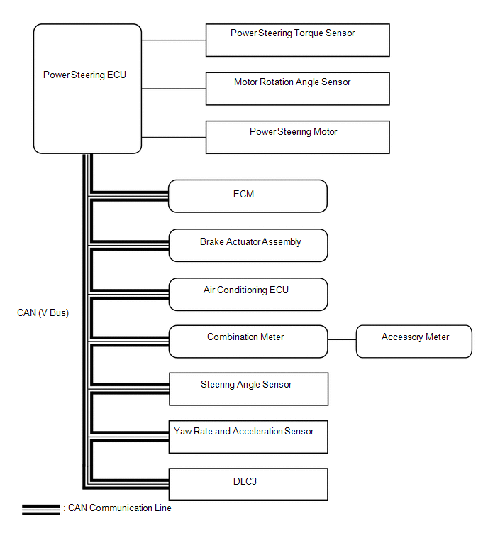
SYSTEM DIAGRAM
|
Transmitting ECU (Transmitter) |
Receiving ECU |
Signal |
Communication Method |
|---|---|---|---|
|
ECM |
Power Steering ECU |
|
CAN |
|
Brake Actuator Assembly (Skid Control ECU) |
Power Steering ECU |
|
CAN |
|
Steering Angle Sensor |
Power Steering ECU |
|
CAN |
|
Yaw Rate Sensor and Acceleration Sensor |
Power Steering ECU |
|
CAN |
|
Power Steering ECU |
ECM |
EPS idle up request signal |
CAN |
|
Power Steering ECU |
Air Conditioning ECU |
Loading control level signal |
CAN |
|
Power Steering ECU |
Combination Meter |
|
CAN |
|
Power Steering ECU |
Brake Actuator Assembly (Skid Control ECU) |
|
CAN |
 Precaution
PRECAUTION
1. PRECAUTION FOR DISCONNECTING THE BATTERY CABLE
NOTICE:
When disconnecting the cable from the negative (-) battery terminal, initialize
the following systems after the cable is recon ...
 How To Proceed With Troubleshooting
CAUTION / NOTICE / HINT
HINT:
Use the following procedure to troubleshoot the power steering system.
*: Use the Techstream.
PROCEDURE
1.
VEHICLE BROUGHT ...
Other materials about Toyota Venza:
How To Proceed With Troubleshooting
CAUTION / NOTICE / HINT
HINT:
Use the following procedure to troubleshoot the audio and visual system.
*: Use the Techstream.
PROCEDURE
1.
VEHICLE BROUGHT TO WORKSHOP
NEXT
...
Installation
INSTALLATION
PROCEDURE
1. INSTALL FUEL INJECTOR ASSEMBLY
HINT:
Perform "Inspection After Repair" after replacing the fuel injector assembly
(See page ).
(a) Apply a light coat of gasoline or spindle oil to new O-rings, and
then ...
Inspection
INSPECTION
PROCEDURE
1. INSPECT UNIVERSAL JOINT SPIDER ASSEMBLY
(a) Check the spider bearing axial play by turning the flange while holding
the shaft tightly.
HINT:
If necessary, replace the propeller with center bearing shaft assembly. ...

0.1393