Toyota Venza: Driver Side Solar Sensor Short Circuit (B14A2)
DESCRIPTION
.png)
The solar sensor is installed on the upper side of the instrument panel. It detects sunlight to control air conditioning AUTO mode. The output voltage from the solar sensor varies in accordance with the amount of sunlight. When the amount of sunlight increases, the output voltage increases. As the sunlight decreases, the output voltage decreases. The A/C amplifier detects changes in the output voltage from the solar sensor.
|
DTC No. |
DTC Detection Condition |
Trouble Area |
|---|---|---|
|
B14A2 |
Short in driver side solar sensor circuit |
|
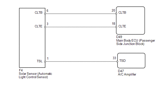
WIRING DIAGRAM
CAUTION / NOTICE / HINT
HINT:
If DTC B1244 is output together with other DTCs, troubleshoot DTC B1244 first
(See page .gif) ).
).
PROCEDURE
|
1. |
READ VALUE USING TECHSTREAM |
(a) Connect the Techstream to the DLC3.
(b) Turn the ignition switch to ON.
(c) Turn the Techstream on.
(d) Enter the following menus: Body / Air Conditioner / Data List.
(e) Check the value(s) by referring to the table below.
Air Conditioner|
Tester Display |
Measurement Item/Range |
Normal Condition |
Diagnostic Note |
|---|---|---|---|
|
Solar Sensor (D side) |
Driver side solar sensor / Min.: 0 Max.: 255 |
Driver side solar sensor value increases as brightness increases |
- |
OK:
The display is as specified in the Normal Condition column.
|
Result |
Proceed to |
|---|---|
|
NG |
A |
|
OK (When troubleshooting according to Problem Symptoms Table) |
B |
|
OK (When troubleshooting according to the DTC) |
C |
| B | .gif) |
PROCEED TO NEXT SUSPECTED AREA SHOWN IN PROBLEM SYMPTOMS TABLE |
| C | |
REPLACE A/C AMPLIFIER |
|
.gif)
|
2. |
CHECK HARNESS AND CONNECTOR (POWER SOURCE CIRCUIT) |
|
(a) Disconnect the solar sensor connector. |
|
(b) Measure the voltage according to the value(s) in the table below.
Standard Voltage:
|
Tester Connection |
Condition |
Specified Condition |
|---|---|---|
|
F4-6 (CLTB) - F4-3 (CLTE) |
Ignition switch off |
Below 1 V |
|
F4-6 (CLTB) - F4-3 (CLTE) |
Ignition switch ON |
11 to 14 V |
|
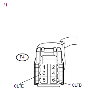
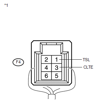
*1 |
Front view of wire harness connector (to Solar Sensor) |
| NG | |
GO TO STEP 5 |
|
|
3. |
CHECK HARNESS AND CONNECTOR (SOLAR SENSOR - A/C AMPLIFIER) |
|
(a) Disconnect the solar sensor connector. |
|
|
(b) Disconnect the A/C amplifier connector. |
|
(c) Measure the resistance according to the value(s) in the table below.
Standard Resistance:
|
Tester Connection |
Condition |
Specified Condition |
|---|---|---|
|
D47-33 (TSD) - F4-1 (TSL) |
Always |
Below 1 Ω |
|
D47-33 (TSD) - Body ground |
Always |
10 kΩ or higher |
|
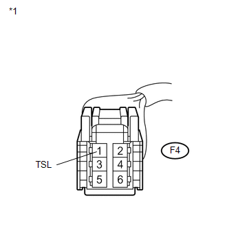
*1 |
Front view of wire harness connector (to Solar Sensor) |
|
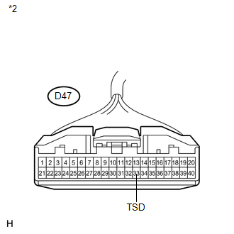
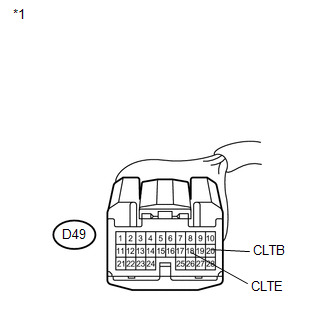
*2 |
Front view of wire harness connector (to A/C Amplifier) |
| NG | |
REPAIR OR REPLACE HARNESS OR CONNECTOR |
|
|
4. |
INSPECT SOLAR SENSOR |
|
(a) Remove the solar sensor. |
|
(b) Reconnect the solar sensor connector.
(c) Turn the ignition switch to ON.
(d) Measure the voltage according to the value(s) in the table below.
Standard Voltage:
|
Tester Connection |
Condition |
Specified Condition |
|---|---|---|
|
F4-1 (TSL) - F4-3 (CLTE) |
Sensor is subjected to electric light |
0.8 to 4.3 V |
|
F4-1 (TSL) - F4-3 (CLTE) |
Sensor is covered with a cloth |
Below 0.8 V |
NOTICE:
- The connection procedure for using a digital tester such as a TOYOTA electrical tester is shown above. When using an analog tester, connect the negative (-) lead to terminal 2 and the positive (+) lead to terminal 6 of the solar sensor.
- While using the battery during inspection, do not bring the positive and negative tester probes too close to each other as a short circuit may occur.
HINT:
- Use an incandescent light for inspection. Bring it within about 30 cm (11.8 in.) of the solar sensor.
- As the inspection light is moved away from the sensor, the voltage decreases.
|
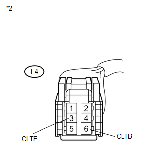
*1 |
Component with harness connected (Solar Sensor) |
| OK | |
REPLACE A/C AMPLIFIER |
| NG | |
REPLACE SOLAR SENSOR |
|
5. |
CHECK HARNESS AND CONNECTOR (MAIN BODY ECU - SOLAR SENSOR) |
|
(a) Disconnect the main body ECU connector. |
|
|
(b) Measure the resistance according to the value(s) in the table below. Standard Resistance:
|
|
| OK | |
REPLACE MAIN BODY ECU |
| NG | |
REPAIR OR REPLACE HARNESS OR CONNECTOR |
 Front Passenger Side Solar Sensor Short Circuit (B14A3)
DESCRIPTION
The solar sensor is installed on the upper side of the instrument panel. It detects
sunlight to control air conditioning AUTO mode. The output voltage from the solar
sensor varies i ...
 Compressor Solenoid Circuit (B1451/51)
DESCRIPTION
In this circuit, the A/C compressor receives a refrigerant compression demand
signal from the A/C amplifier.
Based on this signal, the A/C compressor changes the amount of compressor o ...
Other materials about Toyota Venza:
Fail-safe Chart
FAIL-SAFE CHART
1. FAIL-SAFE FUNCTION
If the following malfunctions occur, the AWD control ECU will stop the
function of 4WD control system or partly change the function to control
the system.
If a malfunction occurs in the senso ...
Removal
REMOVAL
PROCEDURE
1. PRECAUTION
NOTICE:
After turning the ignition switch off, waiting time may be required before disconnecting
the cable from the negative (-) battery terminal. Therefore, make sure to read the
disconnecting the cable from the negativ ...
Installation
INSTALLATION
CAUTION / NOTICE / HINT
HINT:
Use the same procedure for the RH side and LH side.
The procedure listed below is for the LH side.
PROCEDURE
1. INSTALL REAR AIRBAG SENSOR
(a) Check that the ignition switch is off.
(b) Check ...

0.1613