Toyota Venza: Components
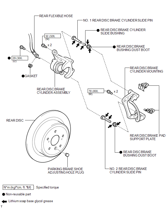
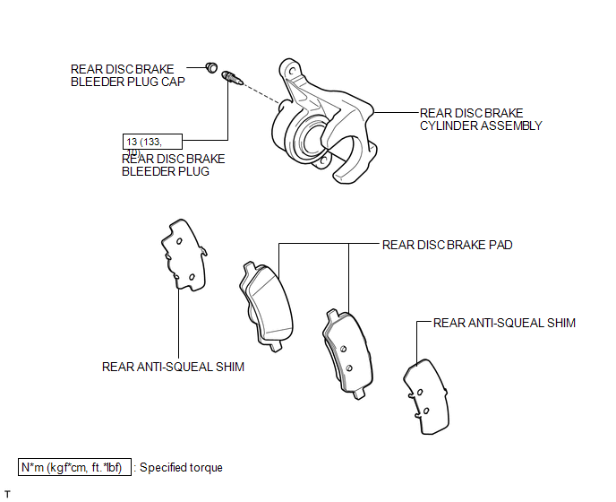
COMPONENTS
ILLUSTRATION
ILLUSTRATION
 Rear Brake
...
 Removal
REMOVAL
CAUTION / NOTICE / HINT
HINT:
Use the same procedure for the LH side and RH side.
The following procedure listed is for the LH side.
PROCEDURE
1. REMOVE REAR WHEEL
2. D ...
Other materials about Toyota Venza:
Abbreviations Used In Manual
ABBREVIATIONS USED IN MANUAL
Abbreviation
Meaning
ABS
Anti-Lock Brake System
A/C
Air Conditioner
AC
Alternating Current
ACC
A ...
Washer Nozzle(for Rear Side)
Components
COMPONENTS
ILLUSTRATION
On-vehicle Inspection
ON-VEHICLE INSPECTION
PROCEDURE
1. INSPECT REAR WASHER NOZZLE
(a) With the engine running, check where the washer fluid hits the windshield.
Standard Measurement
Area
...
Tire Pressure Warning Receiver
Components
COMPONENTS
ILLUSTRATION
Removal
REMOVAL
PROCEDURE
1. DISCONNECT CABLE FROM NEGATIVE BATTERY TERMINAL
NOTICE:
When disconnecting the cable, some systems need to be initialized after the cable
is reconnected (See page ).
2. REMOVE RO ...

0.1335