Toyota Venza: Reassembly
REASSEMBLY
PROCEDURE
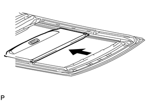
1. INSTALL NO. 1 SUNSHADE TRIM SUB-ASSEMBLY
|
(a) Slide and install the No. 1 sunshade trim sub-assembly. |
|
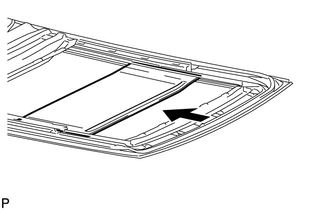
2. INSTALL NO. 2 SUNSHADE TRIM SUB-ASSEMBLY
|
(a) Slide and install the No. 2 sunshade trim sub-assembly. |
|

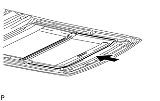
3. INSTALL NO. 3 SUNSHADE TRIM SUB-ASSEMBLY
|
(a) Slide and install the No. 3 sunshade trim sub-assembly. |
|
4. INSTALL NO. 4 SUNSHADE TRIM SUB-ASSEMBLY
|
(a) Slide and install the No. 4 sunshade trim sub-assembly. |
|
|
(b) Install the front sliding roof sunshade stopper LH with the screw. HINT: Use the same procedure for the RH side and the LH side. |
|
.png)
|
(c) Install the center sliding roof sunshade stopper LH with the screw. HINT: Use the same procedure for the RH side and the LH side. |
|
.png)
|
(d) Install the rear sliding roof sunshade stopper LH with the screw. HINT: Use the same procedure for the RH side and the LH side. |
|
.png)
5. INSTALL SLIDING ROOF HOUSING CENTER FRAME
|
(a) Install the sliding roof housing center frame with the 2 nuts. Torque: 7.0 N·m {71 kgf·cm, 62 in·lbf} |
|
.png)
 Disassembly
DISASSEMBLY
PROCEDURE
1. REMOVE SLIDING ROOF HOUSING CENTER FRAME
(a) Remove the 2 nuts and sliding roof housing center frame.
2. REMOVE N ...
 Installation
INSTALLATION
PROCEDURE
1. TEMPORARILY INSTALL SLIDING ROOF HOUSING ASSEMBLY
(a) Temporarily install the sliding roof housing panel with the 18 nuts.
NOTICE:
When installing the housing to ...
Other materials about Toyota Venza:
Customize Parameters
CUSTOMIZE PARAMETERS
1. CUSTOMIZE FUNCTION WITH TECHSTREAM
NOTICE:
Be sure to record the current settings before customizing.
These buzzers should be ON for safe driving. Perform these procedure
only if it is necessary to set the buzzer OFF ...
Oxygen Sensor Heater Control Circuit Low (Bank 1 Sensor 2) (P0037,P0038,P0141,P102D)
DESCRIPTION
Refer to DTC P0136 (See page ).
HINT:
When any of these DTCs are stored, the ECM enters fail-safe mode. The
ECM turns off the heated oxygen sensor heater in fail-safe mode. Fail-safe
mode continues until the ignition switch is t ...
SFR Solenoid Circuit (C0226/21,C0236/22,C0246/23,C0256/24,C1225/25-C1228/28)
DESCRIPTION
These solenoids turn on when signals are received from the skid control ECU and
they control the pressure acting on the wheel cylinders to control the braking force.
DTC Code
DTC Detection Condition
Trouble Area ...

0.1758