Toyota Venza: Illumination for Panel Switch does not Come on with Tail Switch ON
PROCEDURE
|
1. |
CHECK VEHICLE SIGNAL (OPERATION CHECK) |
(a) Enter the "Vehicle Signal Check Mode" screen. Refer to Check Vehicle Signal
in Operation Check (See page .gif) ).
).
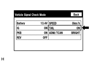
(b) Check that the display changes between ON and OFF according to the light control switch operation.
OK:
|
Light Control Switch |
Display |
|---|---|
|
Tail or head |
ON |
|
Off |
OFF |
HINT:
This display is updated once per second. As a result, it is normal for the display to lag behind the actual switch operation.
| OK | .gif) |
REPLACE RADIO AND DISPLAY RECEIVER ASSEMBLY |
| NG | |
PROCEED TO NEXT SUSPECTED AREA SHOWN IN PROBLEM SYMPTOMS TABLE |
 Radio Broadcast cannot be Received or Poor Reception
PROCEDURE
1.
CHECK RADIO AND DISPLAY RECEIVER ASSEMBLY
(a) Check the radio automatic station search function.
(1) Check the radio automatic station search function b ...
 Display does not Dim when Light Control Switch is Turned ON
PROCEDURE
1.
CHECK IMAGE QUALITY SETTING
(a) Turn the light control switch to the tail or head position.
(b) Check that the daytime screen setting on the display adj ...
Other materials about Toyota Venza:
Diagnosis System
DIAGNOSIS SYSTEM
1. DESCRIPTION
(a) Diagnostic Trouble Codes (DTCs) can be read from the Data Link Connector
3 (DLC3) of the vehicle. When the rear view monitor system seems to be malfunctioning,
use the Techstream to check for malfunctions and to perfor ...
Drive Belt
Components
COMPONENTS
ILLUSTRATION
On-vehicle Inspection
ON-VEHICLE INSPECTION
PROCEDURE
1. INSPECT V-RIBBED BELT
(a) Check the belt for wear, cracks or other signs of damage.
If any of the following defects is found, replace the V-r ...
Power Source Mode does not Change to ON (IG and ACC)
DESCRIPTION
When the engine switch is pushed with the electrical key in the cabin, the power
management control ECU receives signals to change the power source mode.
HINT:
To allow use of the Techstream to inspect the push-button start function when
the ...

0.1317