Toyota Venza: Components
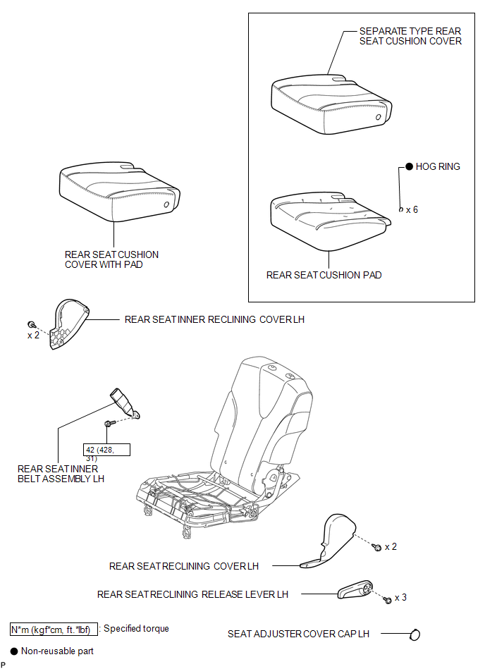
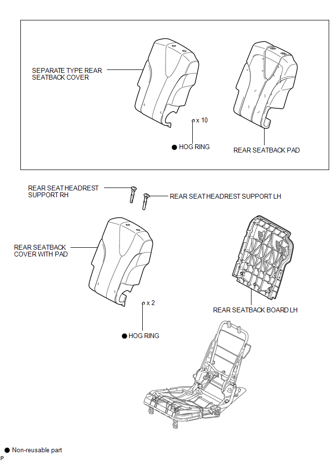
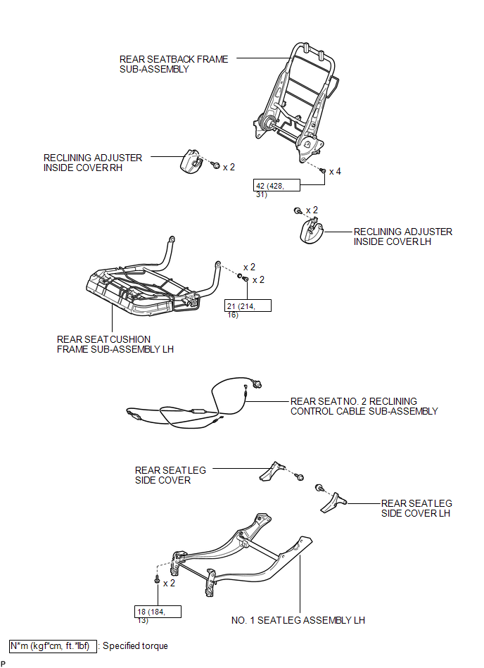
COMPONENTS
ILLUSTRATION
.png)
ILLUSTRATION
ILLUSTRATION
ILLUSTRATION

 Removal
REMOVAL
PROCEDURE
1. REMOVE REAR SEAT HEADREST ASSEMBLY
(a) Press the headrest support button and pull up the headrest as shown
in the illustration to remove it.
...
Other materials about Toyota Venza:
How To Proceed With Troubleshooting
CAUTION / NOTICE / HINT
HINT:
Use the following procedure to troubleshoot the start function.
*: Use the Techstream.
PROCEDURE
1.
VEHICLE BROUGHT TO WORKSHOP
NEXT
...
System Description
SYSTEM DESCRIPTION
1. GENERAL
(a) To assist the driver with parking the vehicle by displaying an image of the
area behind the vehicle, this system has a rear television camera assembly mounted
on the back door. The system displays the image on the naviga ...
Entry Answer-back Buzzer does not Sound
DESCRIPTION
The smart key system uses the wireless door lock buzzer to perform various vehicle
exterior warnings. When the conditions for each warning are met, the certification
ECU (smart key ECU assembly) sends a buzzer request signal to the main body E ...

0.1184