Toyota Venza: Removal
REMOVAL
PROCEDURE
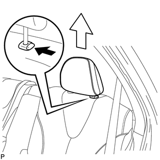
1. REMOVE REAR SEAT HEADREST ASSEMBLY
|
(a) Press the headrest support button and pull up the headrest as shown in the illustration to remove it. |
|
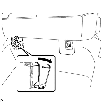
2. REMOVE REAR SEAT INNER TRACK BRACKET COVER
|
(a) Disengage the 3 claws and guide, and remove the rear seat inner track bracket cover as shown in the illustration. |
|
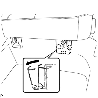
3. REMOVE REAR SEAT OUTER TRACK BRACKET COVER
|
(a) Disengage the 3 claws and guide, and remove the rear seat outer track bracket cover as shown in the illustration. |
|
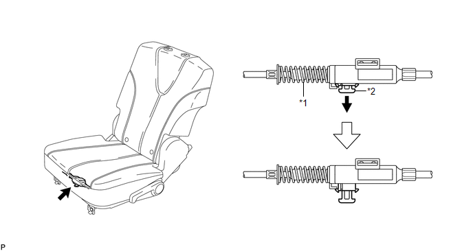
4. DISCONNECT REAR SEAT NO. 2 RECLINING CONTROL CABLE SUB-ASSEMBLY
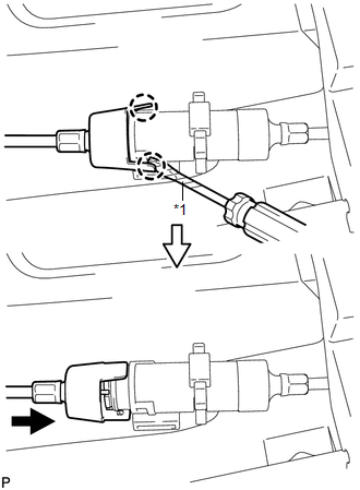
(a) Pull down the adjuster's lock piece to release the lock as shown in the illustration.
 Text in Illustration
|
*1 |
Adjuster Spring |
*2 |
Lock Piece |
|
(b) Using a screwdriver wrapped with protective tape, disengage the 2 claws as shown in the illustration. Text in Illustration
|
|
(c) Lift up the seat track adjusting handle to the uppermost position and hold the handle in this position as shown in the illustration.
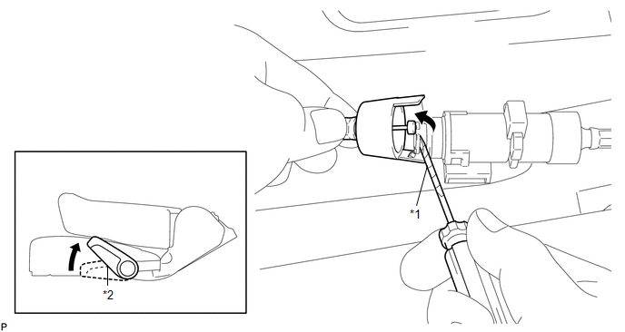 Text in Illustration
|
*1 |
Seat Track Adjusting Handle |
*2 |
Protective Tap |
(d) Using a screwdriver wrapped with protective tape, disconnect the rear seat reclining control cable sub-assembly as shown in the illustration.
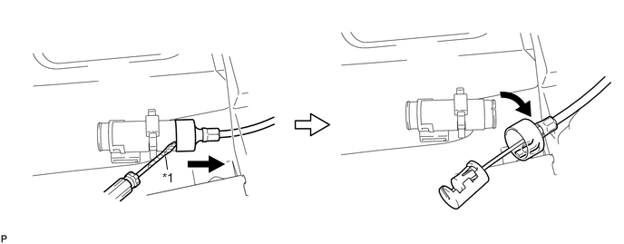 Text in Illustration
|
*1 |
Protective Tape |
(e) Secure the rear seat No. 2 reclining control cable sub-assembly with the carpet hole as shown in the illustration.
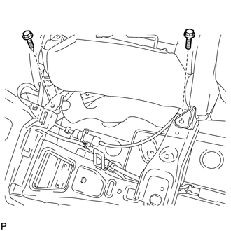
5. REMOVE REAR SEAT ASSEMBLY LH
|
(a) Remove the 2 bolts on the rear side of the seat. |
|
|
(b) Remove the 2 bolts on the front side of the seat. |
|
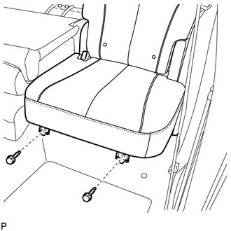
(c) Remove the rear seat assembly LH.
NOTICE:
Be careful not to damage the vehicle body.
 Components
COMPONENTS
ILLUSTRATION
ILLUSTRATION
ILLUSTRATION
ILLUSTRATION
...
 Disassembly
DISASSEMBLY
PROCEDURE
1. REMOVE SEAT ADJUSTER COVER CAP LH
(a) Using a screwdriver wrapped with protective tape, disengage the 3
claws and remove the seat adjuster cover cap LH.
T ...
Other materials about Toyota Venza:
Relay
On-vehicle Inspection
ON-VEHICLE INSPECTION
PROCEDURE
1. INSPECT HORN RELAY (ENGINE ROOM JUNCTION BLOCK ASSEMBLY)
(a) Remove the engine room junction block assembly from the engine room
relay block (See page ).
...
How To Proceed With Troubleshooting
CAUTION / NOTICE / HINT
HINT:
Perform troubleshooting in accordance with the following flowchart.
*: Use the Techstream.
PROCEDURE
1.
VEHICLE BROUGHT TO WORKSHOP
NEXT
...
Installation
INSTALLATION
PROCEDURE
1. INSTALL POWER STEERING ECU ASSEMBLY
(a) Engage the 4 wire harness clamps to the power steering ECU assembly.
(b) Install the power steering ECU assembly with the ...

0.1385