Toyota Venza: Removal
REMOVAL
PROCEDURE
1. RECOVER REFRIGERANT FROM REFRIGERATION SYSTEM
.gif)
2. DISCHARGE FUEL SYSTEM PRESSURE
3. PLACE FRONT WHEELS FACING STRAIGHT AHEAD
4. REMOVE FRONT WHEELS
5. DISCONNECT CABLE FROM NEGATIVE BATTERY TERMINAL
NOTICE:
When disconnecting the cable, some systems need to be initialized after the cable
is reconnected (See page ).
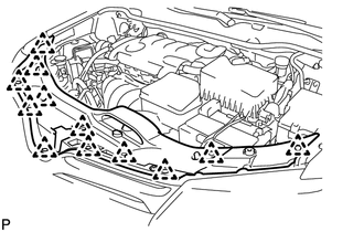
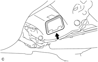
6. REMOVE COOL AIR INTAKE DUCT SEAL
|
(a) Remove the 12 clips and cool air intake duct seal. |
|
7. REMOVE NO. 1 ENGINE UNDER COVER
8. REMOVE NO. 2 ENGINE UNDER COVER
9. SEPARATE FRONT FENDER LINER LH
10. SEPARATE FRONT FENDER LINER RH
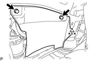
11. REMOVE FRONT FENDER APRON SEAL LH
|
(a) Remove the 2 bolts, clip and front fender apron seal LH. |
|

12. REMOVE FRONT FENDER APRON SEAL RH
|
(a) Remove the 2 bolts, clip and front fender apron seal RH. |
|
13. DRAIN ENGINE OIL
14. DRAIN ENGINE COOLANT
15. DRAIN AUTOMATIC TRANSAXLE FLUID (for 2WD)
16. DRAIN AUTOMATIC TRANSAXLE FLUID (for AWD)
17. DRAIN TRANSFER OIL (for AWD)
18. REMOVE FRONT WIPER ARM HEAD CAP
19. REMOVE FRONT WIPER ARM AND BLADE ASSEMBLY LH
20. REMOVE FRONT WIPER ARM AND BLADE ASSEMBLY RH
21. REMOVE FRONT FENDER TO COWL SIDE SEAL LH
22. REMOVE FRONT FENDER TO COWL SIDE SEAL RH
HINT:
Use the same procedure for the RH side and LH side.
23. REMOVE COWL TOP VENTILATOR LOUVER SUB-ASSEMBLY
24. REMOVE WINDSHIELD WIPER MOTOR AND LINK ASSEMBLY
25. REMOVE OUTER COWL TOP PANEL SUB-ASSEMBLY
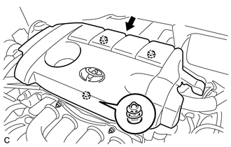
26. REMOVE NO. 1 ENGINE COVER SUB-ASSEMBLY
|
(a) Lift the rear of the No. 1 engine cover sub-assembly to detach the cover from the 2 pins, and then lift the front of the No. 1 engine cover sub-assembly to detach the cover from the pin and remove the No. 1 engine cover sub-assembly. NOTICE: Attempting to disengage both front and rear clips at the same time may cause the No. 1 engine cover sub-assembly to break. |
|
27. REMOVE BATTERY
|
(a) Remove the nut and separate the positive (+) battery terminal. |
|
(b) Loosen the nut and remove the bolt and battery clamp.
(c) Remove the battery and battery tray.
28. REMOVE INLET AIR CLEANER ASSEMBLY
|
(a) Remove the 2 bolts and inlet air cleaner assembly. |
|

29. REMOVE AIR CLEANER CAP SUB-ASSEMBLY
30. REMOVE AIR CLEANER FILTER ELEMENT SUB-ASSEMBLY
(a) Remove the air cleaner filter element sub-assembly.
31. REMOVE AIR CLEANER CASE SUB-ASSEMBLY
|
(a) Disconnect the wire harness clamp. |
|
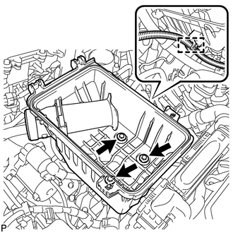
(b) Remove the 3 bolts and air cleaner case sub-assembly.
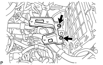
32. REMOVE AIR CLEANER BRACKET
|
(a) Remove the 2 bolts and air cleaner bracket. |
|
33. DISCONNECT NO. 1 RADIATOR HOSE
|
(a) Disconnect the wire harness clamp. |
|
(b) Disconnect the No. 1 radiator hose.
34. DISCONNECT NO. 2 RADIATOR HOSE
|
(a) Disconnect the No. 2 radiator hose. |
|
35. DISCONNECT INLET HEATER WATER HOSE
|
(a) Disconnect inlet heater water hose. |
|

36. DISCONNECT OUTLET HEATER WATER HOSE
|
(a) Disconnect outlet heater water hose. |
|
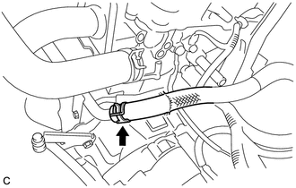
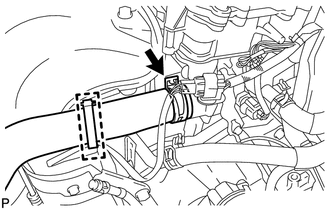
37. DISCONNECT FUEL TUBE SUB-ASSEMBLY
|
(a) Remove the No. 1 fuel pipe clamp. |
|
(b) Pinch the fuel tube connector and then pull out the fuel main tube.
NOTICE:
- Check for dirt and foreign objects on the pipe and around the connector. Clean if necessary and then disconnect the connector.
- Disconnect the connector by hand.
- Do not bend, fold or rotate the nylon tube.
- If the pipe and connector are stuck together, push and pull the connector until it becomes free.
- Put the pipe and connector ends in plastic bags to prevent damage and contamination.
38. DISCONNECT INLET NO. 1 OIL COOLER HOSE
|
(a) Disconnect the inlet No. 1 oil cooler hose. |
|
39. DISCONNECT OUTLET NO. 1 OIL COOLER HOSE
|
(a) Disconnect the outlet No. 1 oil cooler hose. |
|
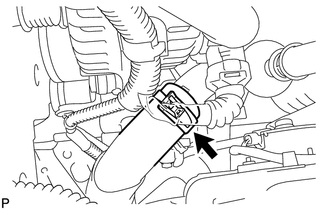
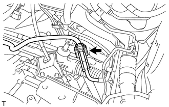
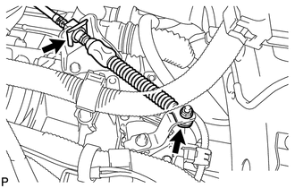
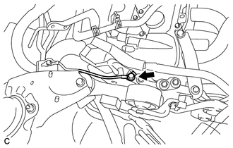
40. DISCONNECT TRANSMISSION CONTROL CABLE ASSEMBLY
|
(a) Remove the clip and nut, and disconnect the transmission control cable assembly from the transaxle. |
|
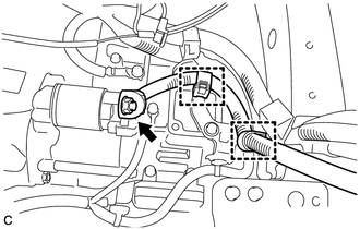
41. DISCONNECT ENGINE WIRE
(a) Remove the No. 1 relay block cover.
|
(b) Disconnect the 2 connectors. |
|
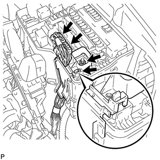
(c) Remove the nut.
(d) Using a screwdriver, unlock the claw and separate the engine wire from the engine room relay block.
|
(e) Disconnect the 2 engine wire clamps. |
|
(f) Remove the bolt and separate the ground cables.
|
(g) Disconnect the ground cable clamp. |
|
(h) Remove the 2 bolts and separate the ground cable.
|
(i) Remove the bolt and separate the ground cable. |
|
|
(j) Disconnect the 2 clamps, remove the nut and separate the positive (+) cable. |
|
|
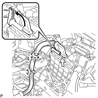
(k) Pull up the lever to disconnect the ECM connector. |
|
(l) Disconnect the 2 clamps.
42. REMOVE NO. 2 ENGINE MOUNTING STAY RH
|
(a) Remove the 2 bolts and No. 2 engine mounting stay RH. |
|
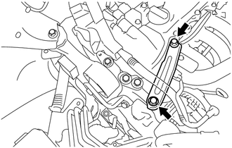
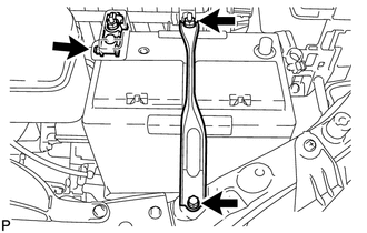
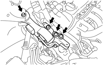
43. REMOVE ENGINE MOVING CONTROL ROD
|
(a) Remove the 4 bolts and engine moving control rod. |
|
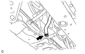
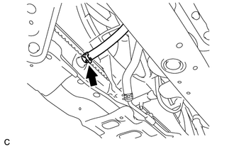
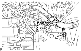
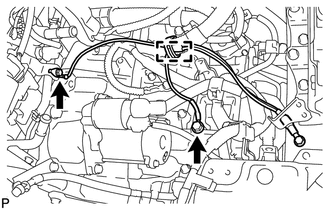
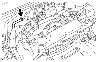
44. DISCONNECT UNION TO CHECK VALVE HOSE
|
(a) Disconnect the 2 union to check valve hoses. |
|
45. DISCONNECT SUCTION HOSE SUB-ASSEMBLY
46. DISCONNECT COOLER REFRIGERANT DISCHARGE HOSE
47. REMOVE TAIL EXHAUST PIPE ASSEMBLY (for AWD)
48. REMOVE CENTER EXHAUST PIPE ASSEMBLY (for AWD)
49. REMOVE PROPELLER WITH CENTER BEARING SHAFT ASSEMBLY (for AWD)
50. REMOVE FRONT EXHAUST PIPE ASSEMBLY
51. SECURE STEERING WHEEL
52. DISCONNECT STEERING INTERMEDIATE SHAFT SUB-ASSEMBLY
53. REMOVE FRONT AXLE SHAFT NUT LH
54. REMOVE FRONT AXLE SHAFT NUT RH
HINT:
Perform the same procedure as for the LH side.
55. SEPARATE FRONT SPEED SENSOR LH
56. SEPARATE FRONT SPEED SENSOR RH
HINT:
Perform the same procedure as for the LH side.
57. SEPARATE TIE ROD ASSEMBLY LH
58. SEPARATE TIE ROD ASSEMBLY RH
HINT:
Perform the same procedure as for the LH side.
59. SEPARATE FRONT STABILIZER LINK ASSEMBLY LH
60. SEPARATE FRONT STABILIZER LINK ASSEMBLY RH
HINT:
Perform the same procedure as for the LH side.
61. SEPARATE FRONT LOWER SUSPENSION ARM LH
62. SEPARATE FRONT LOWER SUSPENSION ARM RH
HINT:
Perform the same procedure as for the LH side.
63. SEPARATE FRONT AXLE ASSEMBLY LH
64. SEPARATE FRONT AXLE ASSEMBLY RH
HINT:
Perform the same procedure as for the LH side.
65. REMOVE FRONT DRIVE SHAFT ASSEMBLY LH
66. REMOVE FRONT DRIVE SHAFT HOLE SNAP RING (for LH Side)
67. REMOVE FRONT DRIVE SHAFT ASSEMBLY RH (for 2WD)
68. REMOVE FRONT DRIVE SHAFT ASSEMBLY RH (for AWD)
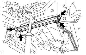
69. REMOVE FRONT FLOOR BRACE
|
(a) Remove the 4 nuts and front floor brace. |
|
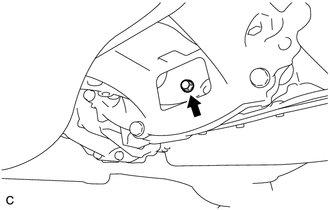
70. REMOVE FLYWHEEL HOUSING UNDER COVER
|
(a) Remove the flywheel housing under cover. |
|
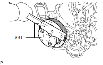
71. REMOVE DRIVE PLATE AND TORQUE CONVERTER SETTING BOLT
|
(a) Using SST, hold the crankshaft pulley. SST: 09213-54015 SST: 09330-00021 HINT: Part number of installation bolt for SST (crankshaft pulley holding tool): 91551-80650 (quantity: 2) |
|
|
(b) Remove the 6 drive plate and torque converter setting bolts. HINT: There will be one black colored bolt. |
|
72. REMOVE ENGINE ASSEMBLY WITH TRANSAXLE
(a) Prepare an engine lifter.
|
(b) Remove the 4 bolts, 2 nuts, and frame side rail plates RH and LH. |
|
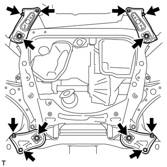
(c) Remove the 4 bolts, 2 nuts, and front suspension member rear braces RH and LH.
(d) Operate the engine lifter, then remove the engine assembly with transaxle from the vehicle.
NOTICE:
Make sure that the engine is clear of all wiring and hoses.
73. REMOVE NO. 1 FRONT STABILIZER BRACKET LH (for AWD)
74. REMOVE NO. 1 FRONT STABILIZER BRACKET RH (for AWD)
HINT:
Perform the same procedure as for the LH side.
75. REMOVE FRONT STABILIZER BAR (for AWD)
76. REMOVE STEERING LINK ASSEMBLY (for AWD)
77. INSTALL ENGINE HANGERS
|
(a) Install the 2 engine hangers with the 2 bolts as shown in the illustration. Text in Illustration
Torque: 43 N·m {438 kgf·cm, 32 ft·lbf} HINT: Fit the fork part of the No. 2 engine hanger onto the rib of the cylinder head. |
|
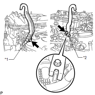
(b) Attach the engine sling device and hang the engine with the chain block.
78. REMOVE V-RIBBED BELT
79. REMOVE GENERATOR ASSEMBLY
80. REMOVE COMPRESSOR ASSEMBLY WITH PULLEY
81. REMOVE STARTER ASSEMBLY
82. SEPARATE REAR ENGINE MOUNTING INSULATOR ASSEMBLY (for AWD)
|
(a) Remove the 2 bolts and separate the rear engine mounting insulator assembly from the rear engine mounting bracket. |
|
83. REMOVE FRONT FRAME ASSEMBLY
|
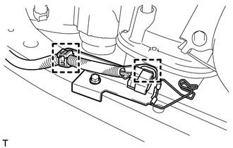
(a) Disconnect the 2 clamps with the engine wire. |
|
|
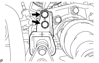
(b) Remove the 2 nuts and separate the engine mounting insulators RH and LH. |
|
|
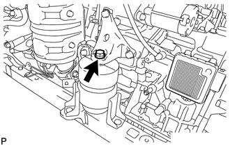
(c) Remove the bolt and separate the front engine mounting insulator. |
|
(d) Remove the front frame assembly from the engine assembly with transaxle.
84. REMOVE FRONT ENGINE MOUNTING INSULATOR ASSEMBLY
|
(a) Remove the 2 hole plugs. |
|
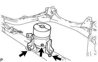
(b) Remove the 3 nuts and front engine mounting insulator assembly.
HINT:
Perform this procedure only when replacement of the engine mounting insulator is necessary.
85. REMOVE ENGINE MOUNTING INSULATOR LH
|
(a) Remove the 2 hole plugs. |
|
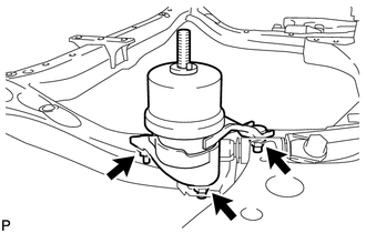
(b) Remove the 3 nuts and engine mounting insulator LH.
HINT:
Perform this procedure only when replacement of the engine mounting insulator is necessary.
86. REMOVE ENGINE MOUNTING INSULATOR RH
|
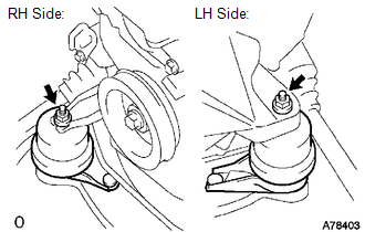
(a) Remove the 2 hole plugs. |
|
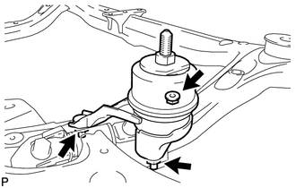
(b) Remove the 3 nuts and engine mounting insulator RH.
HINT:
Perform this procedure only when replacement of the engine mounting insulator is necessary.
87. REMOVE REAR ENGINE MOUNTING INSULATOR ASSEMBLY (for AWD)
|
(a) Remove the 2 hole plugs. |
|
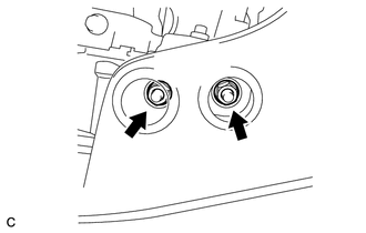
(b) Remove the 2 nuts and transverse engine mounting insulator.
HINT:
Perform this procedure only when replacement of the engine mounting insulator is necessary.
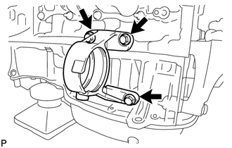
88. REMOVE TRANSFER STIFFENER PLATE RH (for AWD)
|
(a) Remove the 4 bolts and transfer stiffener plate RH. |
|
89. REMOVE AUTOMATIC TRANSAXLE ASSEMBLY (for 2WD)
90. REMOVE AUTOMATIC TRANSAXLE ASSEMBLY (for AWD)
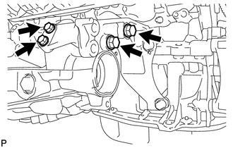
91. REMOVE ENGINE MOUNTING BRACKET RH
|
(a) Remove the 3 bolts and engine mounting bracket RH. |
|
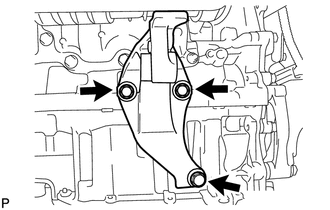
92. REMOVE DRIVE SHAFT BEARING BRACKET (for 2WD)
|
(a) Remove the 3 bolts and drive shaft bearing bracket. |
|
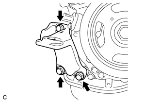
93. REMOVE REAR ENGINE MOUNTING BRACKET (for AWD)
|
(a) Remove the 3 bolts and rear engine mounting bracket. |
|
94. REMOVE DRIVE PLATE AND RING GEAR SUB-ASSEMBLY
95. REMOVE ENGINE WIRE
(a) Remove the engine wire.
96. INSTALL ENGINE ON ENGINE STAND
(a) Install the engine onto an engine stand with the bolts.
97. REMOVE ENGINE HANGERS
|
(a) Remove the 2 bolts and No. 1 and No. 2 engine hangers. Text in Illustration
|
|
 Components
COMPONENTS
ILLUSTRATION
ILLUSTRATION
ILLUSTRATION
ILLUSTRATION
ILLUSTRATION
ILLUSTRATION
ILLUSTRATION
ILLUSTRATION
ILLUSTRATION
...
 Installation
INSTALLATION
CAUTION / NOTICE / HINT
HINT:
Perform "Inspection After Repair" after replacing the engine assembly (See page
).
PROCEDURE
1. INSTALL ENGINE HANGERS
2. REMOVE ENGINE ...
Other materials about Toyota Venza:
Inspection
INSPECTION
PROCEDURE
1. INSPECT FRONT SEAT FRAME WITH ADJUSTER LH
(a) Check operation of the seat frame (slide motor).
(1) w/ Memory:
Check if the seat frame moves smoothly when the battery is connected
to the slide motor connector termin ...
Removal
REMOVAL
CAUTION / NOTICE / HINT
NOTICE:
When disconnecting the steering intermediate shaft assembly and pinion shaft
of steering gear assembly, be sure to place matchmarks before servicing.
PROCEDURE
1. PLACE FRONT WHEELS FACING STRAIGHT AHEAD
2. SECUR ...
Problem Symptoms Table
PROBLEM SYMPTOMS TABLE
NOTICE:
After replacing the stereo component tuner assembly of vehicles subscribed to
pay-type satellite radio broadcasts, XM radio ID registration is necessary (w/ SDARS
System).
HINT:
Use the table below to help determi ...

0.1818