Toyota Venza: Inspection
INSPECTION
PROCEDURE
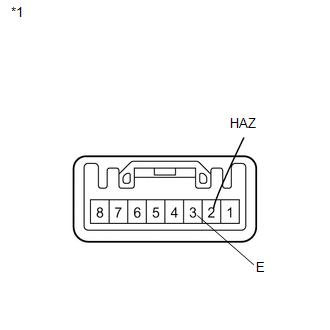
1. INSPECT DRIVE MONITOR SWITCH
|
(a) Measure the resistance according to the value(s) in the table below. Standard Resistance:
If the result is not as specified, replace the driver monitor switch. |
|
 Components
COMPONENTS
ILLUSTRATION
ILLUSTRATION
ILLUSTRATION
...
 Removal
REMOVAL
PROCEDURE
1. REMOVE UPPER CONSOLE PANEL SUB-ASSEMBLY (w/o Seat Heater System)
2. REMOVE UPPER CONSOLE PANEL SUB-ASSEMBLY (w/ Seat Heater System)
3. REMOVE NO. 2 CONSOLE BOX CARPET
...
Other materials about Toyota Venza:
Reassembly
REASSEMBLY
PROCEDURE
1. INSTALL COOLER DRYER
(a) Using pliers, install a new cooler dryer to the modulator.
(b) Apply sufficient compressor oil to the O-ring and fitting surfaces
of t ...
Disposal
DISPOSAL
CAUTION / NOTICE / HINT
CAUTION:
Before performing pre-disposal deployment of any SRS component, review and closely
follow all applicable environmental and hazardous material regulations. Pre-disposal
deployment may be considered hazardous mate ...
Satellite Radio Broadcast cannot be Received
CAUTION / NOTICE / HINT
NOTICE:
Some satellite radio broadcasts require payment. A contract must be made between
a satellite radio company and the user. If the contract expires, it will not be
possible to listen to the broadcast.
PROCEDURE
1 ...

0.1299