Toyota Venza: Back Door Opener Switch
Components
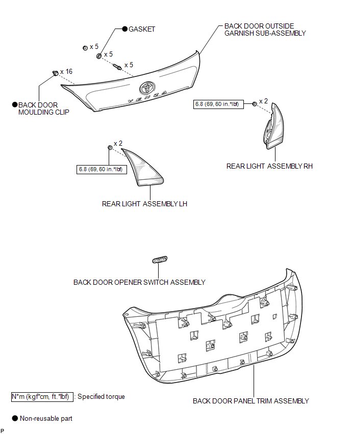
COMPONENTS
ILLUSTRATION
Removal
REMOVAL
PROCEDURE
1. REMOVE BACK DOOR PANEL TRIM ASSEMBLY
.gif)
2. REMOVE REAR LIGHT ASSEMBLY LH
3. REMOVE REAR LIGHT ASSEMBLY RH
HINT:
Use the same procedure for the RH side and LH side.
4. REMOVE BACK DOOR OUTSIDE GARNISH SUB-ASSEMBLY
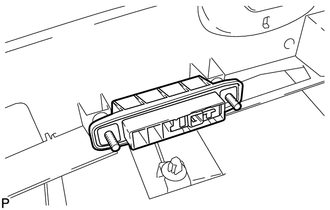
5. REMOVE BACK DOOR OPENER SWITCH ASSEMBLY
|
(a) Remove the back door opener switch assembly. |
|
Inspection
INSPECTION
PROCEDURE
1. INSPECT BACK DOOR OPENER SWITCH ASSEMBLY
(a) Check operation of the opener switch.
(1) Measure the resistance according to the value(s) in the table below.
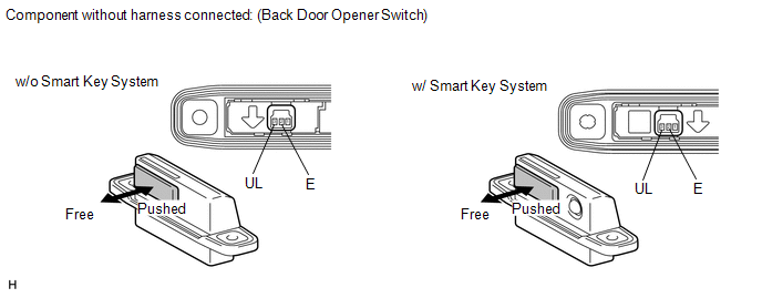
Standard resistance:
|
Tester Connection |
Switch Position |
Specified Condition |
|---|---|---|
|
2(E) - 3(UL) |
Back door opener switch not pushed (OFF) |
10 kΩ or higher |
|
2(E) - 3(UL) |
Back door opener switch pushed (ON) |
Below 1 Ω |
If the result is not specified, replace the back door opener switch assembly.
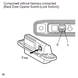
(b) Check operation of the lock switch (w/ Smart Key System).
|
(1) Measure the resistance according to the value(s) in the table below. Standard resistance:
If the result is not specified, replace the back door opener switch assembly. |
|
Installation
INSTALLATION
PROCEDURE
1. INSTALL BACK DOOR OPENER SWITCH ASSEMBLY
|
(a) Install the back door opener switch assembly. |
|
.png)
2. INSTALL BACK DOOR OUTSIDE GARNISH SUB-ASSEMBLY
.gif)
3. INSTALL REAR LIGHT ASSEMBLY LH
4. INSTALL REAR LIGHT ASSEMBLY RH
HINT:
Use the same procedure for the RH side and LH side.
5. INSTALL BACK DOOR PANEL TRIM ASSEMBLY
 Back Door Closer does not Operate
DESCRIPTION
When the back door closer does not operate, one of the following may be the cause:
1) improper fit of the back door, or a foreign object is stuck in the back door
or 2) initialization ...
 Back Door Support
Components
COMPONENTS
ILLUSTRATION
Removal
REMOVAL
PROCEDURE
1. REMOVE BACK DOOR STAY ASSEMBLY
NOTICE:
Avoid touching the piston rod as much as possible to prevent foreign
ma ...
Other materials about Toyota Venza:
ECU Power Source Circuit
DESCRIPTION
This circuit provides power to operate the transponder key ECU assembly.
WIRING DIAGRAM
CAUTION / NOTICE / HINT
NOTICE:
If the transponder key ECU assembly is replaced, register the key and ECU communication
ID (See page ).
PROCEDURE
...
Satellite Radio Broadcast cannot be Received
CAUTION / NOTICE / HINT
NOTICE:
Some satellite radio broadcasts require payment. A contract must be made between
a satellite radio company and the user. If the contract expires, it will not be
possible to listen to the broadcast.
PROCEDURE
1 ...
Installation
INSTALLATION
PROCEDURE
1. INSTALL PARK/NEUTRAL POSITION SWITCH ASSEMBLY
(a) Move the shift lever to N.
(b) Align the protrusions of the park/neutral position switch.
Text in Illustration
*1
Protrusion
...

0.1495